CLUTCH PEDAL(for LHD) ADJUSTMENT
PROCEDURE
-
INSPECT AND ADJUST CLUTCH PEDAL
-
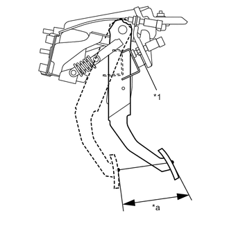
Text in Illustration *1 Lock Nut *a Pedal stroke If the full stroke of the clutch pedal sub-assembly is not within the specified value, loosen the lock nuts of the clutch switch assembly and adjust the full stroke of the clutch pedal sub-assembly with the clutch switch assembly.
Pedal stroke 110 to 115 mm (4.331 to 4.528 in.) - Torque:
- 8.0 N*m { 82 kgf*cm, 71 in.*lbf }
Note
When adjusting the full stroke of clutch pedal sub-assembly, do not turn the clutch switch assembly.
Tech Tips
If the clutch switch assembly cannot adjust the full stroke of clutch pedal sub-assembly to the specified value, adjust it by turning the clutch master cylinder push rod.
-
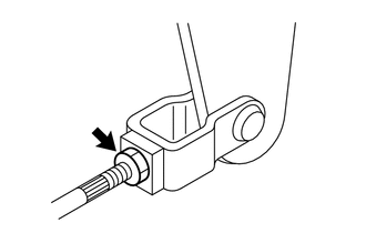
Loosen the push rod lock nuts of the clutch master cylinder assembly.
-
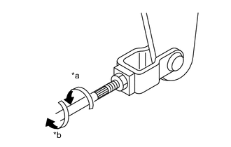
Text in Illustration *a In the Longer Direction *b In the Shorter Direction Rotate the clutch master cylinder push rod to adjust.
-
Make sure that the clutch pedal sub-assembly contacts the clutch pedal stopper when the clutch pedal sub-assembly is at the maximum stroke position.
-
Make sure that the clutch pedal sub-assembly contacts the clutch switch side when the pedal is released.
-
Turn the clutch master cylinder push rod to shorten until a clearance is gained on the clutch switch side.
-
Turn the clutch master cylinder push rod to lengthen until the clutch pedal sub-assembly contacts the clutch switch assembly.
-
Text in Illustration *a In the Longer Direction *b In the Shorter Direction Turn further in the direction that will shorten the clutch master cylinder push rod by 270°.
-
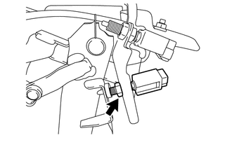
Check that the clevis pin moves smoothly by moving it to the left and right directions.
-
Tighten the clutch master cylinder push rod lock nut of the clutch master cylinder assembly.
- Torque:
- 9.8 N*m { 100 kgf*cm, 87 in.*lbf }
-
Depress and release the clutch pedal sub-assembly two or three times to ensure that the clutch pedal sub-assembly and the release lever operate smoothly. If the clutch pedal sub-assembly and the release lever do not operate smoothly, bleed the air from the clutch line.
-
Measure the clutch pedal sub-assembly full stroke length again to ensure that it is within specifications. If it is not within specifications, repeat the adjustment procedures again from the beginning.
Pedal stroke 110 to 115 mm (4.331 to 4.528 in.)
-
-
INSPECT CLUTCH PEDAL SUB-ASSEMBLY
-
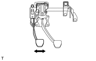
Move the clutch pedal sub-assembly in the lateral direction with a force of approximately 10 N (1.0 kgf, 2.2 lbf) to check that the clutch pedal sub-assembly deflection is within the service limit.
Maximum play 4.0 (0.158 in.) If the play exceeds the maximum, replace the clutch pedal sub-assembly.
-