COUNTER GEAR INSPECTION

PROCEDURE
-
INSPECT NO. 2 TRANSMISSION HUB SLEEVE
-
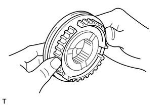
Check that the spline gear edges of the No. 2 transmission hub sleeve are not worn down.
Tech Tips
If it shows any sign of wear, replace the No. 2 transmission hub sleeve with a new one.
-
Install the No. 2 transmission hub sleeve to the No. 2 transmission clutch hub, and then check that it slides smoothly.
Tech Tips
If it does not slide smoothly, replace the No. 2 transmission hub sleeve and No. 2 transmission clutch hub with a new one.
-
-
INSPECT NO. 2 TRANSMISSION HUB SLEEVE CLEARANCE
-
Using a vernier caliper, measure the claw width of the No. 2 gear shift fork.
Standard width 7.9 to 8.0 mm (0.311 to 0.315 in.) Minimum width 7.9 mm (0.311 in.) Tech Tips
If the width is less than the minimum, replace the No. 2 gear shift fork with a new one.
-
Using a vernier caliper, measure the groove of the No. 2 transmission hub sleeve, and then calculate the clearance with the No. 2 gear shift fork.
Standard clearance 0.15 to 0.35 mm (0.00590 to 0.0138 in.) Maximum clearance 0.35 mm (0.0138 in.) Tech Tips
If the clearance exceeds the maximum, replace both the No. 2 gear shift fork and No. 2 transmission hub sleeve with a new ones.
-
-
INSPECT NO. 1 SYNCHRONIZER RING
-
Apply manual transmission gear oil to the taper cone of the counter shaft 4th gear, and then hold the No. 1 synchronizer ring in position with your hand to measure the clearance between the No. 1 synchronizer ring and counter shaft 4th gear by using a feeler gauge.
Standard clearance 0.8 to 1.6 mm (0.0314 to 0.0629 in.) Maximum clearance 1.6 mm (0.0629 in.) Note
Check the entire circumference of the gear.
Tech Tips
If the clearance exceeds the maximum, replace the No. 1 synchronizer ring with a new one.
-
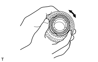
Apply manual transmission gear oil to the taper cone of the counter shaft 4th gear, and then hold the No. 1 synchronizer ring in position with your hand to check that it does not slide in the circumferential direction.
Tech Tips
If the ring slides, replace the No. 1 synchronizer ring with a new one.
-
-
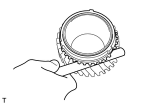
INSPECT NO. 3 SYNCHRONIZER RING SET
-
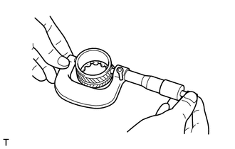
Apply manual transmission gear oil to the taper cone of the counter shaft 3rd gear and No. 3 synchronizer ring set, and then hold the No. 3 synchronizer ring set in position with your hand to measure the clearance between the No. 3 synchronizer ring set and the counter shaft 3rd gear by using a feeler gauge.
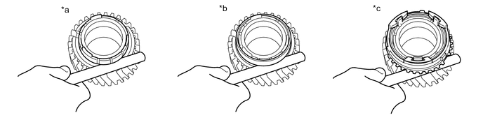
Text in Illustration *a Inner *b Middle *c Outer - - Standard Clearance Location Standard clearance mm (in.) Inner 0.4 to 1.2 (0.0157 to 0.0472) Middle 0.3 to 1.3 (0.0118 to 0.0512) Outer 0.8 to 1.8 (0.0315 to 0.0709) Note
Check the entire circumference of the gear.
Tech Tips
If the result is not as specified, replace the No. 3 synchronizer ring set with a new one.
-
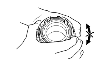
Apply manual transmission gear oil to the taper cone of the counter shaft 3rd gear, and then hold the No. 3 synchronizer ring set in position with your hand to check that it does not slide in the circumferential direction.
Tech Tips
If the No. 3 synchronizer ring set slides, replace the No. 3 synchronizer ring set with a new one.
-
-
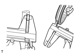
INSPECT COUNTER SHAFT
-
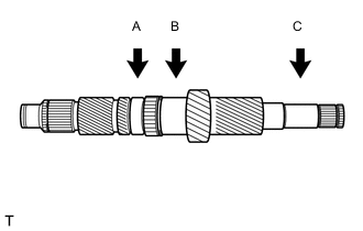
Using a micrometer, measure the outer diameter of each location.
Standard Outer Diameter Part Standard outer diameter mm (in.) Minimum outer diameter mm (in.) A 39.284 to 39.300 (1.54661 to 1.54721) 39.284 (1.54661) B 37.984 to 38.000 (1.49543 to 1.49606) 37.984 (1.49543) C 24.987 to 25.000 (0.98374 to 0.98425) 24.987 (0.98374) Tech Tips
If the diameter is less than the minimum, replace the counter shaft with a new one.
-
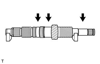
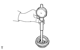
Using V-block and a dial gauge, measure the runout of each location as shown in the illustration.
Standard runout 0.03 mm (0.00118 in.) or less Tech Tips
If the runout exceeds the standard, replace the counter shaft with a new one.
-
-
INSPECT COUNTER SHAFT 3RD GEAR
-
Using a cylinder gauge, measure the inside diameter of the counter shaft 3rd gear.
Standard inside diameter 43.015 to 43.040 mm (1.69350 to 1.69448 in.) Maximum inside diameter 43.040 mm (1.69448 in.) Tech Tips
If the inside diameter exceeds the maximum, replace the counter shaft 3rd gear with a new one.
-
-
INSPECT COUNTER SHAFT 4TH GEAR
-
Using a cylinder gauge, measure the inside diameter of the counter shaft 4th gear.
Standard inside diameter 46.315 to 46.340 mm (1.82425 to 1.82441 in.) Maximum inside diameter 46.340 mm (1.82441 in.) Tech Tips
If the inside diameter exceeds the maximum, replace the counter shaft 4th gear with a new one.
-
-
REMOVE 4TH GEAR BEARING INNER RACE
-
Using a micrometer, measure the outside diameter of the 4th gear bearing inner race.
Standard outside diameter 46.225 to 46.250 mm (1.81988 to 1.82087 in.) Minimum outside diameter 46.225 mm (1.81988 in.) Note
Do not measure the oil groove.
Tech Tips
If the outside diameter is less than the minimum, replace the 4th gear bearing inner race with a new one.
-