OUTPUT SHAFT REASSEMBLY

PROCEDURE
-
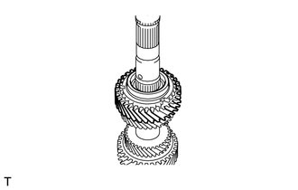
INSTALL REVERSE GEAR
-
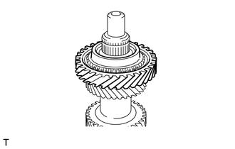
Apply manual transmission gear oil to the mounting point of the output shaft, reverse gear bearing and inside surface and taper cone of the reverse gear.
-
Install the reverse gear bearing and reverse gear to the output shaft.
-
-
INSTALL NO. 3 TRANSMISSION HUB SLEEVE
-
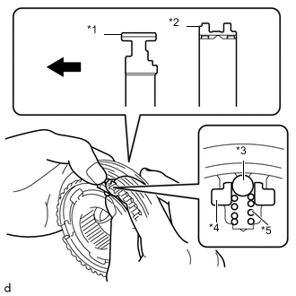
Text in Illustration *1 No. 3 Transmission Clutch Hub *2 No. 3 Transmission Hub Sleeve *3 Ball *4 No. 1 Synchromesh Shifting Key *5 No. 1 Synchromesh Shifting Key Spring 
Front Side Apply manual transmission gear oil to the moving parts of the No. 3 transmission clutch hub.
-
As shown in the illustration, install the No. 3 transmission hub sleeve to the No. 3 transmission clutch hub. And install the 3 No. 1 synchromesh shifting keys and 3 synchromesh shifting key springs all together, and then install the 3 balls.
Tech Tips
-
Install the ball while holding down the No. 1 synchromesh shifting key spring.
-
After the installation, let the No. 1 synchromesh shifting key spring settle down.
-
-
-
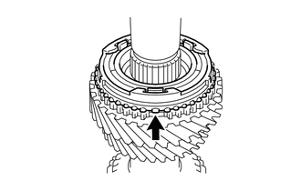
INSTALL NO. 3 TRANSMISSION CLUTCH HUB
-
Install the No. 3 synchronizer ring to the reverse gear.
-
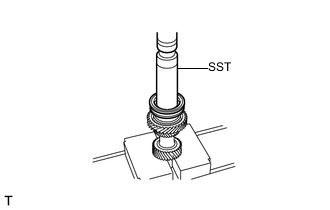
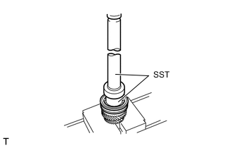
Using SST and a press, install the No. 3 transmission clutch hub.
- SST
- 09309-37010
Tech Tips
-
Align the No. 3 transmission clutch hub and the No. 3 synchronizer ring so that they can fit together.
-
After the No. 3 transmission clutch hub is installed, check that the No. 3 synchronizer ring moves in the thrust direction.
-
Make sure to press fit the No. 3 transmission clutch hub until it touches the output shaft.
-
-
INSTALL SHAFT SNAP RING (for No. 3 transmission clutch hub)
-
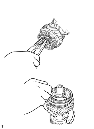
Select a shaft snap ring that is suitable to retain the specific thrust clearance between the No. 3 transmission clutch hub and shaft snap ring.
Standard clearance 0 to 0.1 mm (0 to 0.00394 in.) Tech Tips
Select the thickest shaft snap ring possible for installation.
Shaft Snap Ring Thickness Part No. Thickness mm (in.) Mark SU003-03581 1.80 (0.07086) A SU003-03582 1.85 (0.07283) B SU003-03583 1.90 (0.07480) C SU003-03584 1.95 (0.07677) D SU003-03585 2.00 (0.07874) E SU003-03586 2.05 (0.08070) F -
Using a snap ring expander, install a new shaft snap ring to the output shaft.
-
-
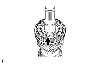
INSTALL 2ND GEAR
-
Apply manual transmission gear oil to the mounting point of the output shaft, 2nd gear needle roller bearing and inside surface and taper cone of the reverse gear.
-
Install the 2nd gear needle roller bearing and 2nd gear to the output shaft.
-
-
INSTALL NO. 1 TRANSMISSION HUB SLEEVE
-

Text in Illustration *1 No. 1 Transmission Clutch Hub *2 No. 1 Transmission Hub Sleeve *3 Ball *4 No. 1 Synchromesh Shifting Key *5 No. 1 Synchromesh Shifting Key Spring Front Side Apply manual transmission gear oil to the moving parts of the No. 1 transmission clutch hub.
-
As shown in the illustration, install the No. 1 transmission hub sleeve to the No. 1 transmission clutch hub. And install the 3 No. 1 synchromesh shifting keys and 3 synchromesh shifting key springs all together, and then install the 3 balls.
Tech Tips
-
Install the ball while holding down the No. 1 synchromesh shifting key spring.
-
After the installation, let the No. 1 synchromesh shifting key spring settle down.
-
-
-
INSTALL NO. 1 TRANSMISSION CLUTCH HUB
-
Align and install the No. 1 synchronizer ring set (for 2nd gear) in the position, as shown in the illustration.
Tech Tips
-
Align the middle ring claw with the groove in the 2nd gear.
-
Align the inner ring claw with the groove in the outer ring.
-
-
Using SST and a press, install the No. 1 transmission clutch hub.
- SST
- 09309-35010
- 09631-12090
Tech Tips
-
Align the No. 1 transmission clutch hub and the No. 1 synchronizer ring set (for 2nd gear) so that they can fit together.
-
After the No. 1 transmission clutch hub is installed, check that the No. 1 synchronizer ring set (for 2nd gear) moves in the thrust direction.
-
Make sure to press fit the No. 1 transmission clutch hub until it touches the output shaft.
-
Align and install the No. 1 synchronizer ring set (for 1st gear) in the position, as shown in the illustration.
Tech Tips
-
Align the outer ring claw with the groove in No. 1 transmission clutch hub.
-
Align the inner ring claw with the groove in the outer ring.
-
-
-
INSTALL 1ST GEAR
-
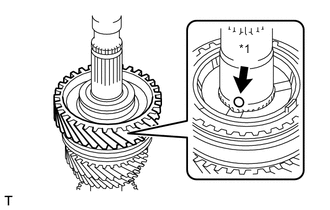
Text in Illustration *1 1st Shift Restrict Ball After the output shaft is installed, apply manual transmission gear oil to the mounting point of the output shaft, needle roller bearing inner race, and inside surface and taper cone of the 1st gear.
-
Install the 1st shift restrict ball, 1st gear, 1st gear needle roller bearing and 1st gear bearing inner race to the output shaft.
Tech Tips
Align the middle ring claw with the groove in the 1st gear.
-
-
INSTALL REAR OUTPUT SHAFT BEARING
-
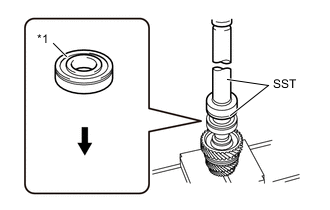
Text in Illustration *1 Rear Output Shaft Bearing Front Side Using SST and a press, as shown in the illustration, install the rear output shaft bearing.
- SST
- 09309-35010
- 09316-60011 ( 09316-00021 )
Tech Tips
Make sure to press fit the rear output shaft bearing until it touches the 1st gear bearing inner race.
-
-
INSTALL 6TH GEAR
-
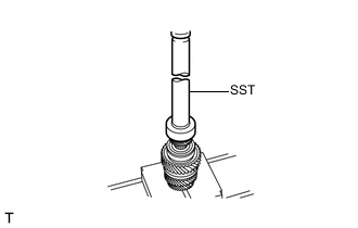
Using SST and a press, install the 6th gear.
- SST
- 09309-35010
Tech Tips
Make sure to press fit the 6th gear until it touches the rear output shaft bearing.
-
-
INSTALL SHAFT SNAP RING (for 6th gear)
-
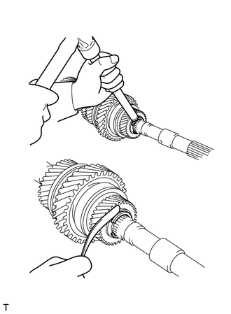
Select a shaft snap ring that is suitable to retain the specific thrust clearance between the 6th gear and shaft snap ring.
Standard clearance 0 to 0.11 mm (0 to 0.00433 in.) Tech Tips
Select the thickest shaft snap ring possible for installation.
Shaft Snap Ring Thickness Part No. Thickness mm (in.) Mark SU003-03564 2.67 (0.10511) A SU003-03565 2.73 (0.10748) B SU003-03566 2.79 (0.10984) C SU003-03567 2.85 (0.11220) D SU003-03568 2.91 (0.11456) E SU003-03569 2.97 (0.11692) F SU003-03570 3.03 (0.11929) G SU003-03571 3.09 (0.12165) H SU003-03572 3.15 (0.12401) J SU003-03573 3.21 (0.01053) K SU003-03574 3.27 (0.12874) L -
Using a brass bar and hammer, install a new shaft snap ring to the output shaft.
-