INPUT SHAFT DISASSEMBLY

PROCEDURE
-
INSPECT NEEDLE ROLLER BEARING
-
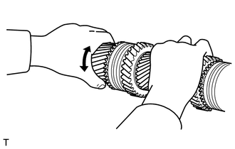
Install the input shaft to the output shaft, and then check the needle roller bearing.
Standard Abnormal fitting, interfering, abnormal noise, or looseness should not be found. Tech Tips
If any abnormality is found, replace the needle roller bearing with a new one.
-
-
INSPECT RADIAL CLEARANCE
-
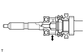
Install the input shaft to the output shaft, and then using a dial indicator, measure the radial clearance.
Standard clearance 0.029 to 0.072 mm (0.00114 to 0.00283 in.) Maximum clearance 0.072 mm (0.00283 in.) Tech Tips
If the clearance exceeds the maximum, replace the needle roller bearing and output shaft with a new ones.
-
-
INSPECT FRONT INPUT SHAFT BEARING
-
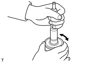
Check the front input shaft bearing.
Standard Abnormal fitting, interfering, abnormal noise, or looseness should not be found. Tech Tips
If any abnormality is found, replace the front input shaft bearing with a new one.
-
-
REMOVE NEEDLE ROLLER BEARING
-
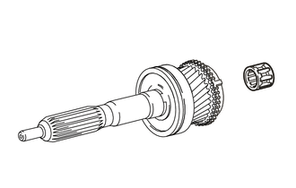
Remove the needle roller bearing from the input shaft.
-
-
REMOVE NO. 2 SYNCHRONIZER RING
-
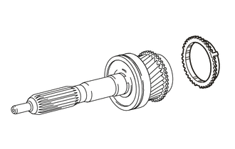
Remove the No. 2 synchronizer ring from the input shaft.
-
-
REMOVE FRONT INPUT SHAFT BEARING
-
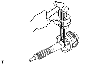
Using 2 screwdrivers and a hammer, remove the shaft snap ring from the input shaft.
Note
Use a cloth to prevent the shaft snap ring from popping out.
-
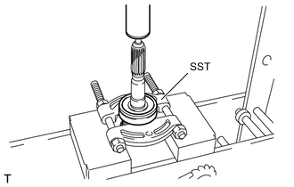
Using SST and a press, remove the front input shaft bearing from the input shaft.
- SST
- 09950-00020
-