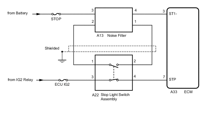
CRUISE CONTROL SYSTEM Stop Light Switch Circuit
DESCRIPTION
When the brake pedal is released, terminal STP of the ECM receives positive (+) battery voltage through the ECU IG2 fuse. While depressing the brake pedal, the stop light switch sends a signal to terminals STP and ST1- of the ECM. The ECM cancels cruise control drive when terminal STP receives the signal.
WIRING DIAGRAM
CAUTION / NOTICE / HINT
Tech Tips
Stop light switch assembly conditions can be checked using the GTS.
-
Connect the GTS to the DLC3.
-
Turn the ignition switch to ON.
-
Turn the GTS on.
-
Enter the following menus: Powertrain / Cruise Control / Data List / Stop Light Switch 1 and Stop Light Switch 2.
Cruise Control Brake Pedal Operation Stop Light Switch 1 Stop Light Switch 2 Depressed ON ON Released OFF OFF
PROCEDURE
-
CHECK ECM (TERMINAL VOLTAGE)
-
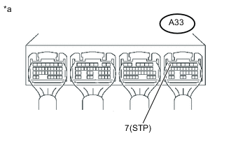
Text in Illustration *a Component with harness connected
(ECM)
Turn the ignition switch to ON.
-
Measure the voltage according to the value(s) in the table below.
Standard voltage Tester Connection Condition Specified Condition A33-7 (STP) - Body ground Brake pedal released 11 to 14 V Brake pedal depressed Below 1 V
NG 
CHECK TERMINAL VOLTAGE (POWER SOURCE OF STOP LIGHT SWITCH ASSEMBLY) Click here
OK 
-
-
CHECK ECM (TERMINAL VOLTAGE)
-
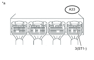
Text in Illustration *a Component with harness connected
(ECM)
Turn the ignition switch to ON.
-
Measure the voltage according to the value(s) in the table below.
Standard voltage Tester Connection Condition Specified Condition A33-3 (ST1-) - Body ground Brake pedal depressed 11 to 14 V Brake pedal released Below 1 V
OK 
PROCEED TO NEXT SUSPECTED AREA SHOWN IN PROBLEM SYMPTOMS TABLE Click here
NG
CHECK TERMINAL VOLTAGE (POWER SOURCE OF STOP LIGHT SWITCH ASSEMBLY) Click here
-
-
CHECK TERMINAL VOLTAGE (POWER SOURCE OF STOP LIGHT SWITCH ASSEMBLY)
-
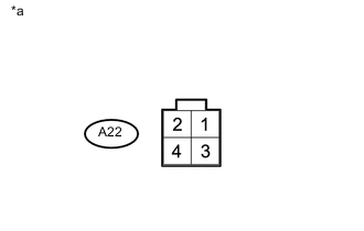
Text in Illustration *a Front view of wire harness connector
(to Stop Light Switch Assembly)
Disconnect the stop light switch assembly connector.
-
Measure the voltage according to the value(s) in the table below.
Standard voltage Tester Connection Condition Specified Condition A22-3 - Body ground Ignition switch ON 11 to 14 V
NG
INSPECT ECM POWER SOURCE CIRCUIT Click here
OK
-
-
CHECK HARNESS AND CONNECTOR (ECM - STOP LIGHT SWITCH ASSEMBLY)
-
Disconnect the ECM connector.
-
Disconnect the stop light switch assembly connector.
-
Measure the resistance according to the value(s) in the table below.
Standard resistance (Check for open) Tester Connection Condition Specified Condition A33-7 (STP) - A22-4 Always Below 1 Ω Standard resistance (Check for short) Tester Connection Condition Specified Condition A33-7 (STP) or A22-4 - Body ground Always 10 kΩ or higher
NG
REPAIR OR REPLACE HARNESS AND CONNECTOR
OK
-
-
INSPECT STOP LIGHT SWITCH ASSEMBLY
-
Inspect the stop light switch assembly Click here.
OK
REPLACE ECM Click here
NG
REPLACE STOP LIGHT SWITCH ASSEMBLY Click here
-
-
CHECK TERMINAL VOLTAGE (POWER SOURCE OF STOP LIGHT SWITCH ASSEMBLY)
-
Text in Illustration *a Front view of wire harness connector
(to Stop Light Switch Assembly)
Disconnect the stop light switch assembly connector.
-
Measure the voltage according to the value(s) in the table below.
Standard voltage Tester Connection Condition Specified Condition A22-1 - Body ground Always 11 to 14 V
NG
CHECK HARNESS AND CONNECTOR (NOISE FILTER - STOP LIGHT SWITCH ASSEMBLY) Click here
OK
-
-
CHECK HARNESS AND CONNECTOR (ECM - STOP LIGHT SWITCH ASSEMBLY)
-
Disconnect the ECM connector.
-
Disconnect the stop light switch assembly connector.
-
Measure the resistance according to the value(s) in the table below.
Standard resistance (Check for open) Tester Connection Condition Specified Condition A33-3 (ST1-) - A22-2 Always Below 1 Ω Standard resistance (Check for short) Tester Connection Condition Specified Condition A33-3 (ST1-) or A22-2 - Body ground Always 10 kΩ or higher
NG
CHECK HARNESS AND CONNECTOR (STOP LIGHT SWITCH ASSEMBLY - NOISE FILTER) Click here
OK
-
-
INSPECT STOP LIGHT SWITCH ASSEMBLY
-
Inspect the stop light switch assembly Click here.
OK
REPLACE ECM Click here
NG
REPLACE STOP LIGHT SWITCH ASSEMBLY Click here
-
-
CHECK HARNESS AND CONNECTOR (NOISE FILTER - STOP LIGHT SWITCH ASSEMBLY)
-
Disconnect the stop light switch assembly connector.
-
Disconnect the noise filter connector.
-
Measure the resistance according to the value(s) in the table below.
Standard resistance (Check for open) Tester Connection Condition Specified Condition A22-1 - A13-2 Always Below 1 Ω Standard resistance (Check for short) Tester Connection Condition Specified Condition A22-1 or A13-2 - Body ground Always 10 kΩ or higher
NG
REPAIR OR REPLACE HARNESS AND CONNECTOR
OK
-
-
INSPECT NOISE FILTER
-
Inspect the noise filter Click here.
OK
REPAIR OR REPLACE HARNESS AND CONNECTOR (NOISE FILTER - BATTERY)
NG
REPLACE NOISE FILTER Click here
-
-
CHECK HARNESS AND CONNECTOR (STOP LIGHT SWITCH ASSEMBLY - NOISE FILTER)
-
Disconnect the stop light switch assembly connector.
-
Disconnect the noise filter connector.
-
Measure the resistance according to the value(s) in the table below.
Standard resistance (Check for open) Tester Connection Condition Specified Condition A22-2 - A13-1 Always Below 1 Ω Standard resistance (Check for short) Tester Connection Condition Specified Condition A22-2 or A13-1 - Body ground Always 10 kΩ or higher
NG
REPAIR OR REPLACE HARNESS AND CONNECTOR
OK
-
-
INSPECT NOISE FILTER
-
Inspect the noise filter Click here.
NG
REPLACE NOISE FILTER Click here
OK
-
-
CHECK HARNESS AND CONNECTOR (ECM - NOISE FILTER)
-
Disconnect the ECM connector.
-
Disconnect the noise filter connector.
-
Measure the resistance according to the value(s) in the table below.
Standard resistance (Check for open) Tester Connection Condition Specified Condition A33-3 (ST1-) - A13-4 Always Below 1 Ω Standard resistance (Check for short) Tester Connection Condition Specified Condition A33-3 (ST1-) or A13-4 - Body ground Always 10 kΩ or higher
OK
REPLACE ECM Click here
NG
REPAIR OR REPLACE HARNESS AND CONNECTOR
-