STARTER(for Manual Transmission) INSPECTION

PROCEDURE
-
INSPECT STARTER ASSEMBLY
CAUTION:
As a large electric current passes through the cable during this inspection, a thick cable must be used. If not, the cable may become hot and cause injury.
Note
The following tests must each be performed within 3 to 5 seconds to prevent the coil from burning out.
-
Mount the starter in a vise between aluminum plates.
-
Perform a pull-in test.
-
Remove the nut, and then disconnect the lead wire from terminal C.
-
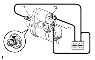
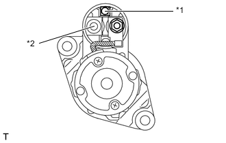
Text in Illustration *1 Body *2 Terminal 50 *3 Terminal C Connect the battery to the starter as shown in the illustration. Check that the clutch pinion gear extends.
If the clutch pinion gear does not move, inspect the magnet starter switch assembly. If the magnet starter switch assembly is not as specified, replace it.
-
-
Perform a holding test.
-
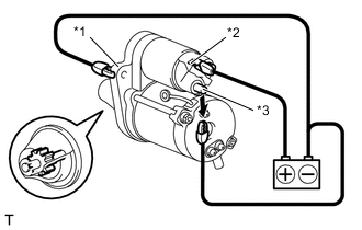
Text in Illustration *1 Body *2 Terminal 50 *3 Terminal C Disconnect the negative (-) terminal lead from terminal C while the conditions specified in the pull-in test above are maintained. Check that the pinion gear remains out.
If the clutch pinion gear returns inward, inspect the magnet starter switch assembly. If the magnet starter switch assembly is not as specified, replace it.
-
-
Inspect the clutch pinion gear return.
-
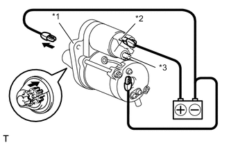
Text in Illustration *1 Body *2 Terminal 50 *3 Terminal C Disconnect the negative (-) terminal lead from the starter body. Check that the clutch pinion gear returns inward.
If the clutch pinion gear does not return inward, inspect the magnet starter switch assembly. If the magnet starter switch assembly is not as specified, replace it.
-
-
Perform an operation test without load.
-
Connect the lead wire to terminal C with the nut.
- Torque:
- 10 N*m { 102 kgf*cm, 7 ft.*lbf }
-
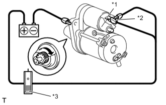
Text in Illustration *1 Terminal 50 *2 Terminal 30 *3 Ammeter Connect the battery and an ammeter to the starter as shown in the illustration.
-
Check that the starter rotates smoothly and steadily while the clutch pinion gear is extended. Then measure the current.
Standard Current Tester Connection Condition Specified Condition Battery positive terminal - Terminal 30 - Terminal 50 11.5 V Below 90 A If the result is not as specified, inspect the starter assembly.
Tech Tips
Inspect the starter armature assembly, starter commutator end frame assembly and magnet starter switch assembly. If there is a malfunction, replace the part and perform again this test.
-
-
-
INSPECT STARTER ARMATURE ASSEMBLY
-
Check the commutator for signs of seizure or stepped wear caused by roughness of the surface. If there is light wear, use sandpaper to repair.
-
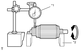
Text in Illustration *1 Dial Gauge *2 V-block Check for runout on the commutator. If excessive, replace the armature.
Standard runout 0.05 mm (0.002 in.) Maximum runout 0.10 mm (0.004 in.) -

Text in Illustration *1 Mold *2 Segment *3 Depth of Mold Check the depth of the segment mold. If it is not within the standard, replace the armature.
Standard depth 0.50 mm (0.020 in.) -

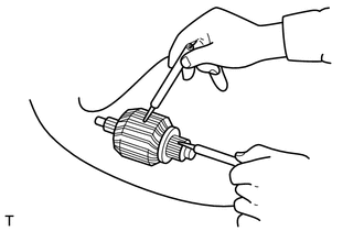
Text in Illustration *1 Steel Sheet *2 Growler Tester Place the armature on the growler tester to check for short circuits. While slowly turning the armature, support the steel sheet for the armature core. If the circuit of the armature is shorted, the steel sheet will vibrate, causing it to move towards the core. When the steel sheet has moved or vibrated, replace the armature.
-
Touch the probe of one side to the commutator segment, and the other probe to the shaft. If there is continuity, replace the armature.
-
-
INSPECT STARTER YOKE ASSEMBLY
-
Make sure that the pole is set at the predetermined position.
-
-
INSPECT STARTER BRUSH HOLDER ASSEMBLY
-
Visually check the brush. If there is any abnormal wear or cracks, replace the brush.
-

Text in Illustration *1 Service Limit Line *2 Brush Measure the length of the brush. If it exceeds the service limits, replace the brush.
Standard length 12.3 mm (0.484 in.) Minimum length 7.0 mm (0.276 in.) -
Check that the brush moves smoothly in the brush holder.
-
Measure the brush spring force with a spring scale. Replace the brush holder if below the service limit.
Standard brush spring force 15.9 to 19.5 N (1.6 to 2.0 kgf, 3.6 to 4.4 lbf) Minimum brush spring force 2.5 N (0.3 kgf, 0.6 lbf)
-
-
INSPECT STARTER CLUTCH SUB-ASSEMBLY
-
Check the gear teeth on the planetary gear, internal gear and starter clutch for wear or damage.
If any of the gears is damaged, replace the starter center bearing clutch sub-assembly.
-
Check the starter clutch pinion gear.
-
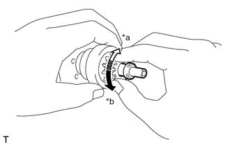
Text in Illustration *a Free *b Lock Hold the starter clutch, rotate the pinion gear clockwise and check that it turns freely. Try to rotate the pinion gear counterclockwise and check that it locks.
If necessary, replace the starter clutch sub-assembly.
-
-
-
INSPECT MAGNET STARTER SWITCH ASSEMBLY
-
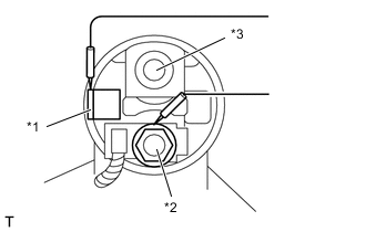
Text in Illustration *1 Terminal 50 *2 Terminal C *3 Terminal 30 Check that there is continuity between terminals 50 and C, and between terminal 50 and ground. Also, check to be sure there is no continuity between terminal C and 30.
Standard Resistance Tester Connection Condition Specified Condition Terminal C - Terminal 50 Always Below 1 Ω Terminal 50 - Switch body Always Below 1 Ω Terminal C - Terminal 30 Always 1 MΩ or higher -
Using a lead wire, connect the switch assembly terminal 50 to the positive terminal of the battery, and the starter body to the ground terminal of the battery. The pinion should be forced to be pushed out on the shaft.
Tech Tips
With the pinion forced to be pushed out on the shaft, the starter motor can sometimes rotate because the current flows, through pull-in coil, to motor. This is not a problem.
-
Text in Illustration *1 Terminal 50 *2 Terminal C Disconnect the connector from terminal C. Then, using a lead wire, connect the positive terminal of the battery and terminal C, and ground terminal to starter body. In this test set up, the pinion should return to its original position even when it is pulled out with a screwdriver.
-