AUTOMATIC TRANSMISSION SYSTEM, Diagnostic DTC:P1817

| DTC Code | DTC Name |
|---|---|
| P1817 | Manual Mode Switch Circuit Malfunction |
DESCRIPTION
A signal from the manual mode switch assembly input into the TCM detects the M position.
| DTC Code | DTC Detection Condition
|
Trouble Area |
|---|---|---|
| P1817 |
|
|
WIRING DIAGRAM
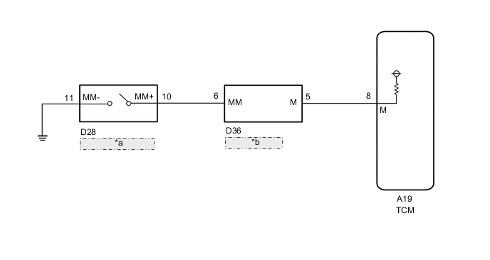
| *a | Manual Mode Switch |
| *b | Shift Position Indicator |
PROCEDURE
-
CHECK MANUAL MODE SWITCH
-
Disconnect the A19 TCM connector.
-
Measure the resistance according to the value(s) in the table below.
Standard Resistance Tester Connection Shift Position Specified Condition A19-8(M) - Body ground M Below 1 Ω A19-8(M) - Body ground Except M 10 kΩ or higher -
Connect the A19 TCM connector.
NG 
CHECK HARNESS AND CONNECTOR (MANUAL MODE SWITCH - SHIFT POSITION INDICATOR) Click here
OK 
-
-
REPLACE TCM
-
Replace the TCM Click here.
NEXT 
PERFORM THE RESET MEMORY Click here
-
-
CHECK HARNESS AND CONNECTOR (MANUAL MODE SWITCH - SHIFT POSITION INDICATOR)
-
Disconnect the D36 shift position indicator connector.
-
Disconnect the D28 manual mode switch connector.
-
Measure the resistance according to the value(s) in the table below.
Standard Resistance Tester Connection Condition Specified Condition D36-6(MM) - D28-10(MM+) Always Below 1 Ω D36-6(MM) - Body ground Always 10 kΩ or higher D28-10(MM+) - Body ground Always 10 kΩ or higher -
Connect the D36 shift position indicator connector.
-
Connect the D28 manual mode switch connector.
NG
REPAIR OR REPLACE HARNESS OR CONNECTOR
OK
-
-
INSPECT MANUAL MODE SWITCH
-
Disconnect the D28 manual mode switch connector.
-
Measure the resistance according to the value(s) in the table below.
Standard Resistance Tester Connection Shift Position Specified Condition D28-10(MM+) - D28-11(MM-) M Below 1 Ω Except M 10 kΩ or higher -
Disconnect the D28 manual mode switch connector.
NG
REPLACE MANUAL MODE SWITCH Click here
OK
-
-
CHECK HARNESS AND CONNECTOR (TCM - SHIFT POSITION INDICATOR)
-
Disconnect the A19 TCM connector.
-
Disconnect the D36 shift position indicator connector.
-
Measure the resistance according to the value(s) in the table below.
Standard Resistance Tester Connection Condition Specified Condition D36-5(M) - A19-8(M) Always Below 1 Ω D36-5(M) - Body ground Always 10 kΩ or higher A19-8(M) - Body ground Always 10 kΩ or higher -
Connect the A19 TCM connector.
-
Connect the D36 shift position indicator connector.
OK
REPLACE SHIFT POSITION INDICATOR Click here
NG
REPAIR OR REPLACE HARNESS OR CONNECTOR
-