AUTOMATIC TRANSMISSION SYSTEM TERMINALS OF ECU

-
CHECK TCM

Tech Tips
Each TCM terminal's standard voltage is shown in the table below.
In the table, first follow the information under "Condition". Look under "Symbols (Terminal No.)" for the terminals to inspected. The standard voltage between the terminals is shown under "Specific Condition".
Use the illustration above as a reference for the TCM terminals.
Terminals No. (Symbols) Wiring Color Terminal Description Condition Specified Condition A19-9(D) - A18-33(E01) BR - B-Y D shift position switch signal Ignition switch ON and shift lever in D and M 11 to 14 V Ignition switch ON and shift lever except in D and M Below 1 V A19-10(R) - A18-33(E01) V - B-Y R shift position switch signal Ignition switch ON and shift lever in R 11 to 14 V Ignition switch ON and shift lever except in R Below 1 V A19-1(SFTD) - A18-33(E01) BE - B-Y Down shift switch signal Ignition switch ON and shift lever in "-" (Down shift) Below 1 V A19-2(SFTU) - A18-33(E02) SB - B-Y Up shift switch signal Ignition switch ON and shift lever in "+" (Up shift) Below 1 V A19-8(M) - A18-33(E01) O-B - B-Y M shift position switch signal Ignition switch ON and shift lever in M 11 to 14 V Ignition switch ON and shift lever except in M Below 1 V A19-3(P) - A18-33(E01) BR - B-Y Park position switch signal Ignition switch ON and shift lever in P 11 to 14 V Ignition switch ON and shift lever except in P Below 1 V A19-21(N) - A18-33(E01) B-G - B-Y Neutral position switch signal Ignition switch ON and shift lever in N 11 to 14 V Ignition switch ON and shift lever except in N Below 1 V A18-13(SLU+) - A18-1(SLU-) LG - LG-Y SLU solenoid signal 2nd, 3rd, 4th, 5th or 6th gear (each gear lock-up, M position) Pulse generation
(See waveform 2)
A18-15(SR) - A18-33(E01) R-B - B-Y SR solenoid signal 1st, 2nd, 3rd or 4th gear 11 to 14 V 5th or 6th gear Below 1 V A18-14(S4) - A18-33(E01) L-W - B-Y S4 solenoid signal 2nd, 5th or 6th gear 11 to 14 V 1st, 3rd or 4th gear Below 1 V A18-6(S3) - A18-33(E01) L-Y - B-Y S3 solenoid signal 1st, 2nd or 3rd gear 11 to 14 V 4th, 5th or 6th gear Below 1 V A18-17(S2) - A18-33(E01) L-O - B-Y S2 solenoid signal 1st, 2nd or 6th gear 11 to 14 V 3rd, 4th or 5th gear Below 1 V A18-7(S1) - A18-33(E01) Y - B-Y S1 solenoid signal 1st gear Below 1 V Except 1st gear 11 to 14 V A18-5(SL2+) - A18-11(SL2-) BR-A - BR-B SL2 solenoid signal Engine idle speed Pulse generation
(See waveform 3)
A18-16(SL1+) - A18-12(SL1-) BR - BR-Y SL1 solenoid signal 5th or 6th gear Pulse generation
(See waveform 4)
A19-18(SP2+) - A19-7(SP2-) B - W Output speed sensor SP2 signal Vehicle speed 20 km/h (12 mph) Pulse generation
(See waveform 6)
A19-17(NT+) - A19-28(NT-) G - L Input speed sensor NT signal Engine idle speed (P or N position) Pulse generation
(See waveform 5)
A18-4(SLT+) - A18-9(SLT-) L-R - R-W SLT solenoid signal Engine idle speed Pulse generation
(See waveform 1)
A18-22(OIL) - A18-23(EOIL) R - G-B ATF temperature sensor signal ATF temperature: 115°C (239°F) or more Below 1 V A18-33(E01) - Body ground B-Y - Body ground Ground Always Below 1 Ω A18-3(E02) - Body ground B-Y - Body ground Ground Always Below 1 Ω A18-29(CANH) - A18-33(E01) B-W - B-Y CAN communication line Ignition switch ON Pulse generation
(See waveform 7)
A18-28(CANL) - A18-33(E01) L - B-Y CAN communication line Ignition switch ON Pulse generation
(See waveform 8)
A18-34(IG1) - A18-33(E01) P - B-Y Starter signal Ignition switch ON 11 to 14 V A18-35(IG2) - A18-33(E01) P - B-Y Starter signal Ignition switch ON 11 to 14 V A18-26(BM) - A18-33(E01) Y-R - B-Y Battery Always 11 to 14 V A19-13(SPORT) - Body ground L - B-Y SPORT switch signal Ignition switch ON and pattern select switch pressed continuously (SPORT) 11 to 14 V Ignition switch ON and pattern select switch released (SPORT) Below 1 V A19-24(SNOW) - Body ground W-R - B-Y SNOW switch signal Ignition switch ON and pattern select switch pressed continuously (SNOW) 11 to 14 V Ignition switch ON and pattern select switch released (SNOW) Below 1 V
-
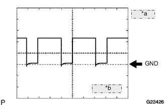
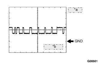
*a 5 V/DIV. *b 1 ms./DIV. Waveform 1
Reference: Terminal A18-4(SLT) - A18-9(SLT-) Tool setting 5 V/DIV., 1 ms./DIV. Vehicle condition Engine idle speed -
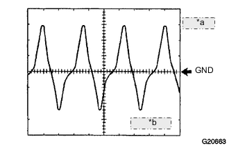
*a 5 V/DIV. *b 1 ms./DIV. Waveform 2
Reference: Terminal A18-13(SLU+) - A18-1(SLU-) Tool setting 5 V/DIV., 1 ms./DIV. Vehicle condition 2nd, 3rd, 4th, 5th or 6th gear (each gear lock-up, M position) -
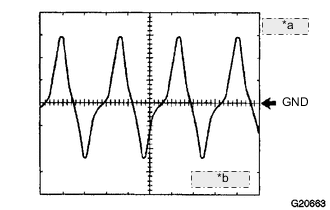
*a 5 V/DIV. *b 1 ms./DIV. Waveform 3
Reference: Terminal A18-5(SL2+) - A18-11(SL2-) Tool setting 5 V/DIV., 1 ms./DIV. Vehicle condition Engine idle speed -
*a 5 V/DIV. *b 1 ms./DIV. Waveform 4
Reference: Terminal A18-16(SL1+) - A18-12(SL1-) Tool setting 5 V/DIV., 1 ms./DIV. Vehicle condition 5th or 6th gear -
*a 5 V/DIV. *b 2 ms./DIV. Waveform 5
Reference: Terminal A19-17(NT+) - A19-28(NT-) Tool setting 5 V/DIV., 2 ms./DIV. Vehicle condition Engine idle speed (P or N position) -
*a 1 V/DIV. *b 2 ms./DIV. Waveform 6
Reference: Terminal A19-18(SP2+) - A19-7(SP2-) Tool setting 1 V/DIV., 2 ms./DIV. Vehicle condition Vehicle speed 20 km/h (12 mph) -
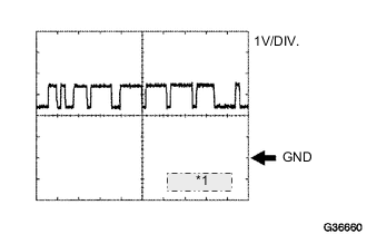
*1 10 ms./DIV Waveform 7
Reference: Terminal A18-29(CANH) - A18-33(E01) Tool setting 1V/DIV., 10 ms./DIV. Vehicle condition Ignition switch ON -
*a 1 V/DIV. *b 10 ms./DIV. Waveform 8
Reference: Terminal A18-28(CANL) - A18-33(E01) Tool setting 1V/DIV., 10 ms./DIV. Vehicle condition Ignition switch ON
-
-
CHECK MAIN BODY ECU (NETWORK GATEWAY ECU) AND INSTRUMENT PANEL JUNCTION BLOCK ASSEMBLY
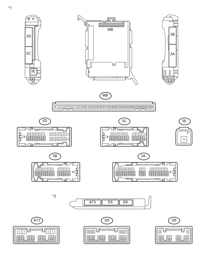
*1 Instrument Panel Junction Block Assembly *2 Main Body ECU (Network Gateway ECU) Tech Tips
Each ECU terminal's standard voltage is shown in the table below.
In the table, first follow the information under "Condition". Look under "Symbols (Terminal No.)" for the terminals to inspected. The standard voltage between the terminals is shown under "Specific Condition".
Use the illustration above as a reference for the ECU terminals.
Terminals No. (Symbols) Wiring Color Terminal Description Condition Specified Condition D5-20(SLS+) - Body ground R Shift lock control unit assembly signal Ignition switch ON, Shift lever P position, and Stop light switch ON 11 to 14 V Ignition switch ON, Shift lever P position, and Stop light switch OFF Below 1 V 3C-8 - Body ground R Stop light switch signal Stop light switch ON 11 to 14 V Stop light switch OFF Below 1 V 3D-23 - Body ground WL Park position switch signal Shift lever except P position 11 to 14 V Shift lever P position Below 1 V Tech Tips
*1: Voltage is input intermittently as this is an intermittent circuit. (Voltage varies between a peak of 7.5 to 14 V and a low of 0 to1.5 V.)