OIL PUMP REMOVAL
PROCEDURE
-
DISCONNECT CABLE FROM NEGATIVE BATTERY TERMINAL
-
DRAIN ENGINE COOLANT
-
REMOVE GENERATOR ASSEMBLY
-
REMOVE INJECTOR DRIVER
-
REMOVE RADIATOR RESERVE TANK ASSEMBLY
-
REMOVE WATER FILLER SUB-ASSEMBLY
-
REMOVE EXHAUST MANIFOLD
-
DISCONNECT RADIATOR OUTLET HOSE
-
DRAIN ENGINE OIL
-
REMOVE WATER PUMP PULLEY
-
REMOVE CRANKSHAFT PULLEY
-
REMOVE INJECTOR COVER (for Bank 1)
-
DISCONNECT ENGINE WIRE
-
Remove the 2 bolts and disconnect the 2 wire harness clamp brackets from the engine assembly.
-
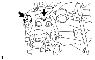
Remove the bolts and disconnect the wire harness clamp bracket from the engine assembly.
-
Disconnect the camshaft position sensor connector.
-
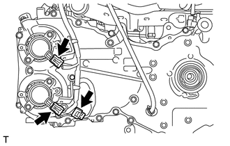
Disconnect the camshaft position sensor connector and 2 camshaft timing oil control valve connectors.
-
Disconnect the camshaft position sensor connector and camshaft timing oil control valve connector.
-
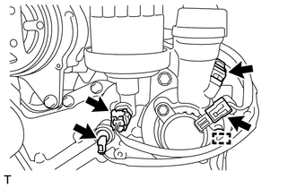
Disconnect the engine oil pressure switch connector and engine oil temperature connector.
-
Disengage the clamp.
-
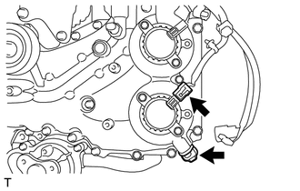
Disconnect the camshaft position sensor connector and camshaft timing oil control valve connector.
-
-
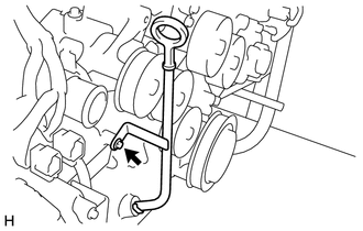
REMOVE OIL LEVEL DIPSTICK GUIDE
-
Remove the oil level dipstick sub-assembly.
-
Remove the bolt and oil level dipstick guide.
-
Remove the O-ring from the oil level dipstick guide.
-
-
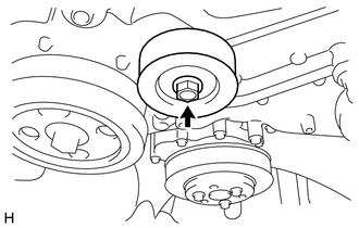
REMOVE NO. 2 IDLER PULLEY SUB-ASSEMBLY
-
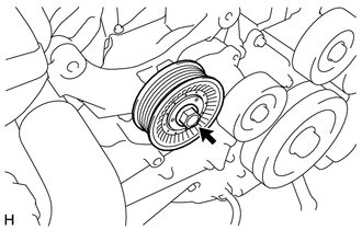
Remove the bolt, washer plate and No. 2 idler pulley sub-assembly.
-
-
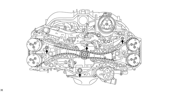
REMOVE V-RIBBED BELT TENSIONER ASSEMBLY
-
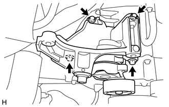
Remove the 4 bolts and V-ribbed belt tensioner assembly.
-
-
REMOVE NO. 1 IDLER PULLEY SUB-ASSEMBLY
-
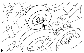
Remove the bolt, washer plate and No. 1 idler pulley sub-assembly.
-
Remove the bolt, washer plate and No. 1 idler pulley sub-assembly.
-
-
REMOVE TIMING CHAIN OR BELT COVER OIL SEAL
-
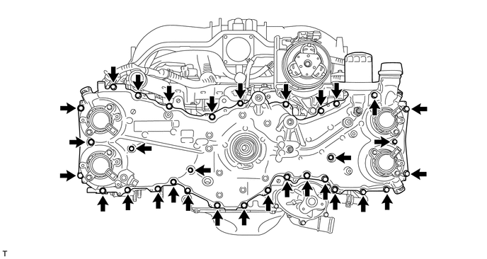
REMOVE TIMING CHAIN OR BELT COVER SUB-ASSEMBLY
-
Remove the 32 bolts.
-
Using a screwdriver with its tip wrapped with protective tape, remove the timing chain or belt cover sub-assembly by prying between the timing chain or belt cover sub-assembly and cylinder head or cylinder block.
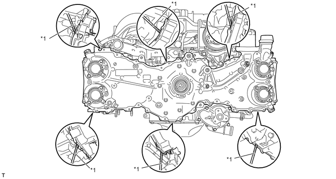
Text in Illustration *1 Protective Tape - - Note
Be careful not to damage the contact surfaces of the cylinder head, cylinder block or chain cover.
-
Remove the 4 O-rings.
-