RELAY ON-VEHICLE INSPECTION
PROCEDURE
-
FAN NO. 1 RELAY
-
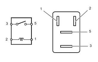
Measure the resistance according to the value(s) in the table below.
Standard Resistance Tester Connection Condition Specified Condition 3 - 5 Battery voltage is not applied between terminals 1 and 2 10 kΩ or higher Battery voltage is applied between terminals 1 and 2 Below 1 Ω
-
If the result is not as specified, replace the relay.
-
-
-
FAN NO. 2 RELAY
-
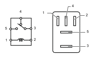
Measure the resistance according to the value(s) in the table below.
Standard Resistance Tester Connection Condition Specified Condition 3 - 4 Battery voltage is not applied between terminals 1 and 2 Below 1 Ω Battery voltage is applied between terminals 1 and 2 10 kΩ or higher 3 - 5 Battery voltage is not applied between terminals 1 and 2 10 kΩ or higher Battery voltage is applied between terminals 1 and 2 Below 1 Ω
-
If the result is not as specified, replace the relay.
-
-
-
FAN NO. 3 RELAY
-
Measure the resistance according to the value(s) in the table below.
Standard Resistance Tester Connection Condition Specified Condition 3 - 5 Battery voltage is not applied between terminals 1 and 2 10 kΩ or higher Battery voltage is applied between terminals 1 and 2 Below 1 Ω
-
If the result is not as specified, replace the relay.
-
-