INTAKE MANIFOLD REASSEMBLY
PROCEDURE
-
INSTALL NO. 2 FUEL DELIVERY PIPE SUB-ASSEMBLY
-
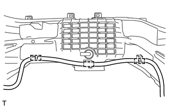
Install the No. 2 fuel delivery pipe sub-assembly to the intake manifold with the 3 clamps.
-
-
INSTALL FUEL DELIVERY PIPE (for Bank 2)
-
Apply a gasoline to the contact surfaces of the new O-ring on each fuel injector assembly.
-
Install a new O-ring to each fuel injector assembly.
-
Install the fuel injector assembly to the intake manifold with fuel delivery pipe.
Note
-
Do not damage the fuel injector assembly or the O-ring.
-
Do not twist the O-ring.
-
-
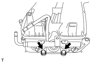
Install the fuel delivery pipe with the 2 bolts.
- Torque:
- 19 N*m { 194 kgf*cm, 14 ft.*lbf }
-
Check that the fuel injectors rotate smoothly.
Note
If the fuel injectors do not rotate smoothly, the probable cause is incorrect installation of the O-rings. Replace the O-rings.
-
Position the fuel injector connector outward.
-
-
INSTALL FUEL DELIVERY PIPE (for Bank 1)
Tech Tips
Use the same procedure described for the fuel delivery pipe (for bank 2).
-
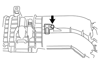
INSTALL CAP (for Automatic Transmission)
-
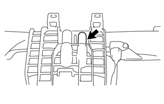
Install the cap to the intake manifold.
-
-
INSTALL PURGE VALVE
-
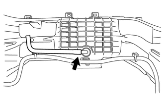
Connect the No. 1 fuel vapor feed hose to the intake manifold.
-
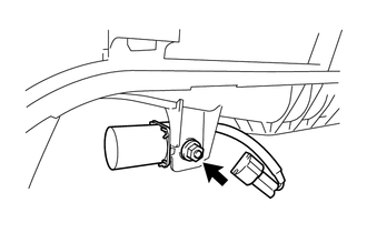
Install the nut and purge valve to the intake manifold.
- Torque:
- 6.4 N*m { 65 kgf*cm, 57 in.*lbf }
-
-
INSTALL MANIFOLD ABSOLUTE PRESSURE SENSOR
-
Apply engine oil to the contact surfaces of the new O-ring on manifold absolute pressure sensor.
-
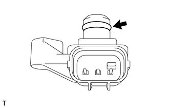
Install a new O-ring to the manifold absolute pressure sensor.
-
Install the manifold absolute pressure sensor to the intake manifold with the bolt.
- Torque:
- 4.0 N*m { 41 kgf*cm, 35 in.*lbf }
-