KEY INTER LOCK SYSTEM Key Cannot be Removed or Inserted
DESCRIPTION
When an ACC signal and a P signal is input, the control unit relay assembly outputs a signal to the key inter lock solenoid.
WIRING DIAGRAM
Refer to System Diagram Click here.
CAUTION / NOTICE / HINT
Note
Inspect the fuses for circuits related to this system before performing the following inspection procedure.
PROCEDURE
-
CHECK WIRE HARNESS AND CONNECTOR (ACC VOLTAGE)
-
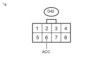
Text in Illustration *a Front view of wire harness connector
(to control unit relay assembly)
Disconnect the D42 control unit relay assembly connector.
-
Measure the voltage according to the value(s) in the table below.
Standard Voltage Tester Connection Switch Condition Specified Condition D42-6 (ACC) - Body ground Ignition switch ON 11 to 14 V
NG 
REPAIR OR REPLACE HARNESS OR CONNECTOR
OK 
-
-
CHECK WIRE HARNESS AND CONNECTOR (CONTROL UNIT RELAY ASSEMBLY - BODY GROUND)
-
Disconnect the D42 control unit relay assembly connector.
-
Measure the resistance according to the value(s) in the table below.
Standard Resistance Tester Connection Condition Specified Condition D42-1 (E) - Body ground Always Below 1 Ω
NG
REPAIR OR REPLACE HARNESS OR CONNECTOR
OK
-
-
INSPECT P SWITCH (FLOOR SHIFT SHIFT LEVER HOUSING)
-
Inspect the P switch (floor shift shift lever housing) Click here.
NG
REPLACE P SWITCH (FLOOR SHIFT SHIFT LEVER HOUSING) Click here
OK
-
-
CHECK WIRE HARNESS AND CONNECTOR (CONTROL UNIT RELAY ASSEMBLY - P SWITCH (FLOOR SHIFT SHIFT LEVER HOUSING)
-
Disconnect the D42 control unit relay assembly connector.
-
Disconnect the D28 P switch (floor shift shift lever housing) connector.
-
Measure the resistance according to the value(s) in the table below.
Standard Resistance (Check for Open) Tester Connection Condition Specified Condition D42-4 (P) - D28-1 (P) Always Below 1 Ω Standard Resistance (Check for Short) Tester Connection Condition Specified Condition D42-4 (P) or D28-1 (P) - Body ground Always 10 kΩ or higher
NG
REPAIR OR REPLACE HARNESS OR CONNECTOR
OK
-
-
CHECK WIRE HARNESS AND CONNECTOR (P SWITCH (FLOOR SHIFT SHIFT LEVER HOUSING) - BODY GROUND)
-
Disconnect the D28 P switch (floor shift shift lever housing) connector.
-
Measure the resistance according to the value(s) in the table below.
Standard Resistance Tester Connection Condition Specified Condition D28-3 (E) - Body ground Always Below 1 Ω
NG
REPAIR OR REPLACE HARNESS OR CONNECTOR
OK
-
-
CHECK KEY INTER LOCK SOLENOID
-
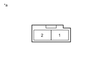
Text in Illustration *a Component without harness connected
(Key Inter Lock Solenoid)
Disconnect the D60 key inter lock solenoid connector.
-
Measure the resistance according to the value(s) in the table below.
Standard Resistance Tester Connection Condition Specified Condition 1 - 2 20°C (68°F) 13.05 to 15.95 Ω
NG
REPLACE KEY INTER LOCK SOLENOID Click here
OK
-
-
CHECK WIRE HARNESS AND CONNECTOR (CONTROL UNIT RELAY ASSEMBLY - KEY INTER LOCK SOLENOID)
-
Disconnect the D42 control unit relay assembly connector.
-
Disconnect the D60 key inter lock solenoid connector.
-
Measure the resistance according to the value(s) in the table below.
Standard Resistance (Check for Open) Tester Connection Condition Specified Condition D42-5 (KLS+) - D60-2 Always Below 1 Ω Standard Resistance (Check for Short) Tester Connection Condition Specified Condition D42-5 (KLS+) or D60-2 - Body ground Always 10 kΩ or higher
NG
REPAIR OR REPLACE HARNESS OR CONNECTOR
OK
-
-
CHECK WIRE HARNESS AND CONNECTOR (KEY INTER LOCK SOLENOID - BODY GROUND)
-
Disconnect the D60 key inter lock solenoid connector.
-
Measure the resistance according to the value(s) in the table below.
Standard Resistance Tester Connection Condition Specified Condition D60-1 - Body ground Always Below 1 Ω
OK
REPLACE CONTROL UNIT RELAY ASSEMBLY Click here
NG
REPAIR OR REPLACE HARNESS OR CONNECTOR
-