FUEL SENDER GAUGE ASSEMBLY INSTALLATION

PROCEDURE
-
INSTALL NO. 2 FUEL SENDER GAUGE ASSEMBLY
-
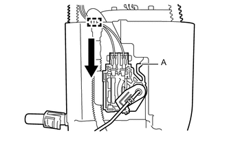
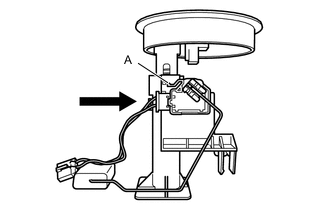
Slide the No. 2 fuel sender gauge assembly downwards and attach the claw labeled A to install the No. 2 fuel sender gauge assembly.
Text in Illustration 
Slide -
Connect the No. 2 fuel sender gauge assembly connector.
-
-
INSTALL FUEL TANK RETURN TUBE
-
Install a new gasket to the fuel tank assembly.
-
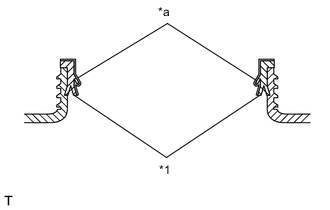
Text in Illustration *1 Gasket *a Application area Apply a light coat of gasoline to a gasket.
Note
-
Apply gasoline in the area indicated in the illustration.
-
Ensure that gasoline does not adhere to the threads of the fuel tank assembly.
-
Check that there is no fuel or foreign matter in the seal section.
-
-
Engage the clamp to install the tube and set the fuel tank return tube into the fuel tank assembly.
Note
Be careful not to bend the arm of the No. 2 fuel sender gauge assembly.
-
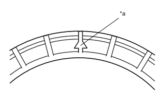
Text in Illustration *a Installation position marks Set the fuel suction tube assembly with pump and gauge within the fuel tank assembly installation position marks.
-
Attach a new sheet ring and fuel pump gauge retainer, and temporarily tighten the fuel pump gauge retainer.
-
Temporarily install SST (plate and 4 claws) to the fuel pump gauge retainer.
- SST
- 09808-14030 ( 09808-01030, 09808-01050 )
- 09808-01071
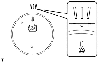
Note
Do not apply a claw of SST at the marked part.
Text in Illustration *a Marked Part Tech Tips
-
Be sure to use SST (claws) as shown in the illustration.
-
Engage SST (claws) securely with the fuel pump gauge retainer ribs to secure SST.
-
While securely pressing SST (claws) against the fuel pump gauge retainer ribs, tighten the 4 bolts.
Tech Tips
Install SST while pressing SST (claws) against the fuel pump gauge retainer (towards the center of SST).
-

Text in Illustration *a Position mark *b Installation position marks Using SST, tighten the fuel pump gauge retainer.
- Torque:
- 85 N*m { 867 kgf*cm, 63 ft.*lbf }
Note
-
Do not use any tools other than those specified in this operation. Damage to the fuel pump gauge retainer or fuel tank may result.
-
Do not press down on SST excessively as this may make the fuel pump gauge retainer hard to rotate, and may damage components.
-
Make sure to rotate SST horizontally. If SST is rotated at an angle, SST may come off.
-
Do not spin SST too fast or use an impact wrench as this may result in damage to components.
-
If SST comes off of the fuel pump gauge retainer, loosen SST (bolts) and reinstall SST.
-
Check that the fuel suction tube assembly with pump and gauge position marks are within the fuel tank assembly installation position marks, as shown in the illustration.
-
After tightening to the specified torque, check that it has been tightened to the correct torque.
Tech Tips
-
Lightly press down on SST to prevent it from separating from the fuel pump gauge retainer. While pressing SST, rotate the handle slowly to tighten the fuel pump gauge retainer.
-
The tips of SST (claws) can be fitted onto the ribs of the fuel pump gauge retainer.
-
-
INSTALL FUEL SENDER GAUGE ASSEMBLY
-
Slide the fuel sender gauge assembly downwards and attach the claw labeled A to install the fuel sender gauge assembly.
Text in Illustration Slide -
Connect the fuel pump harness to the 2 clamps.
-
Connect the fuel sender gauge assembly connector.
-
-
INSTALL FUEL SUCTION TUBE ASSEMBLY WITH PUMP AND GAUGE
-
CONNECT CABLE TO NEGATIVE BATTERY TERMINAL
-
INSPECT FOR FUEL LEAK
-
INSTALL NO. 2 REAR FLOOR SERVICE HOLE COVER
-
INSTALL REAR FLOOR SERVICE HOLE COVER
-
Connect the fuel tank return tube connector.
-
Install the rear floor service hole cover with new butyl tape.
-
-
INSTALL SEPARATE TYPE REAR SEAT CUSHION ASSEMBLY LH
-
INSTALL SEPARATE TYPE REAR SEAT CUSHION ASSEMBLY RH