FUEL PUMP INSTALLATION

PROCEDURE
-
INSTALL FUEL SUCTION TUBE ASSEMBLY WITH PUMP AND GAUGE
-
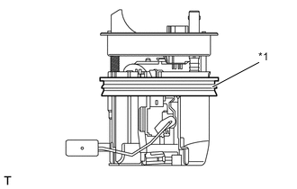
Text in Illustration *1 Gasket Set the new gasket to the fuel suction tube assembly with pump and gauge.
-
Connect the fuel tank vent hose sub-assembly Click here.
Note
-
When connecting the fuel tube connector, do not forcibly pull the fuel return vent tube sub-assembly.
-
Be careful not to bend the arm of the fuel sender gauge assembly.
-
-
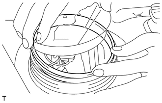
Insert the fuel suction tube assembly with pump and gauge inside the fuel tank assembly, and then attach the new gasket which has already been mounted on the fuel suction tube assembly with pump and gauge to the fuel tank assembly.
Note
Gaps or misplaced attachment of the gasket may cause fuel to leak, so make sure that there are no gaps or misalignments anywhere around the gasket when attaching it to the fuel tank assembly.
-
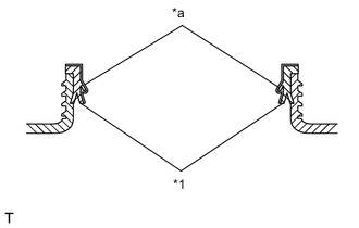
Text in Illustration *1 Gasket *a Application area Apply a light coat of gasoline to a gasket.
Note
-
Apply gasoline in the area indicated in the illustration.
-
Ensure that gasoline does not adhere to the threads of the fuel tank assembly.
-
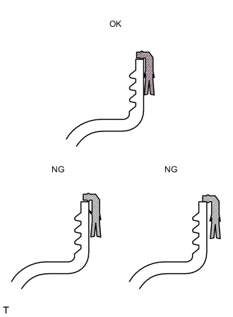
Check that there is no fuel or foreign matter in the seal section.
-
-
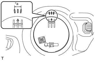
Text in Illustration *a Installation position marks Set the fuel suction tube assembly with pump and gauge within the fuel tank assembly installation position marks.
-
Attach a new sheet ring and fuel pump gauge retainer, and temporarily tighten the fuel pump gauge retainer.
-
Temporarily install SST (plate and 4 claws) to the fuel pump gauge retainer.
- SST
- 09808-14030 ( 09808-01030, 09808-01050 )
- 09808-01071
Note
Do not apply a claw of SST at the marked part.
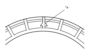
Text in Illustration *a Marked Part Tech Tips
-
Be sure to use SST (claws) as shown in the illustration.
-
Engage SST (claws) securely with the fuel pump gauge retainer ribs to secure SST.
-
While securely pressing SST (claws) against the fuel pump gauge retainer ribs, tighten the 4 bolts.
Tech Tips
Install SST while pressing SST (claws) against the fuel pump gauge retainer (towards the center of SST).
-
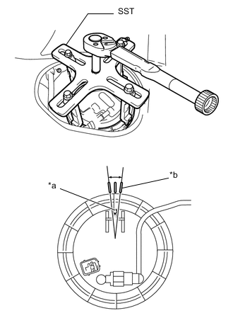
Text in Illustration *a Position mark *b Installation position marks Using SST, tighten the fuel pump gauge retainer.
- Torque:
- 85 N*m { 867 kgf*cm, 63 ft.*lbf }
Note
-
Do not use any tools other than those specified in this operation. Damage to the fuel pump gauge retainer or fuel tank may result.
-
Do not press down on SST excessively as this may make the fuel pump gauge retainer hard to rotate, and may damage components.
-
Make sure to rotate SST horizontally. If SST is rotated at an angle, SST may come off.
-
Do not spin SST too fast or use an impact wrench as this may result in damage to components.
-
If SST comes off of the fuel pump gauge retainer, loosen SST (bolts) and reinstall SST.
-
Check that the fuel suction tube assembly with pump and gauge position marks are within the fuel tank assembly installation position marks, as shown in the illustration.
-
After tightening to the specified torque, check that it has been tightened to the correct torque.
Tech Tips
-
Lightly press down on SST to prevent it from separating from the fuel pump gauge retainer. While pressing SST, rotate the handle slowly to tighten the fuel pump gauge retainer.
-
The tips of SST (claws) can be fitted onto the ribs of the fuel pump gauge retainer.
-
Engage the clamp to install the fuel tank main tube to the fuel tank assembly.
-
Connect the fuel tank main tube Click here.
-
-
CONNECT CABLE TO NEGATIVE BATTERY TERMINAL
-
INSPECT FOR FUEL LEAK
-
INSTALL NO. 2 REAR FLOOR SERVICE HOLE COVER
-
Connect the fuel suction tube assembly with pump and gauge connector.
-
Install the No. 2 rear floor service hole cover with new butyl tape.
-
-
INSTALL SEPARATE TYPE REAR SEAT CUSHION ASSEMBLY LH