FUEL INJECTOR(for Direct Injection) INSTALLATION

PROCEDURE
-
INSTALL FUEL INJECTOR SEAL
-
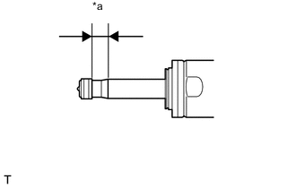
Text in Illustration *a Clean Area Apply engine conditioner to the injector area shown in the illustration. Using a piece of cloth, remove the carbon deposits from the injector and its grooves.
Note
-
Do not clean the tip of the injector.
-
Do not use a wire brush to clean the injector.
-
If an injector is dropped or the tips of the injectors are struck, replace it with a new one.
-
-
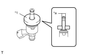
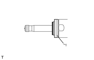
Text in Illustration *1 SST (Guide) *a Tapered Inner Portion Apply engine oil to the injector contact surface of SST (guide). Then attach SST (guide) to the injector with the tapered inner portion facing the tip of the injector, as shown in the illustration.
- SST
- 09260-39021 ( 09261-03020 )
-
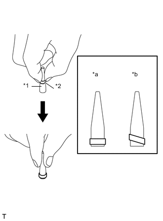
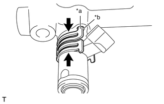
Text in Illustration *1 SST (holder) *2 Injector Seal *a CORRECT *b INCORRECT Install a new injector seal to SST (holder).
- SST
- 09260-39021 ( 09261-03011 )
Note
Be careful not to install the injector seal to SST (holder) at an angle. Doing so will stretch the seal and correcting this problem is very complicated.
-
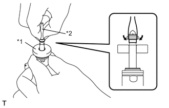
Text in Illustration *1 SST (Guide) *2 SST (Holder) Install SST (holder with injector seal) to the tip of the injector. Slide the seal downward into the injector groove (injector connector side) with your fingers, as shown in the illustration.
- SST
- 09260-39021 ( 09261-03011, 09261-03020 )
Tech Tips
Check that the seal covers the circumference of the injector groove as shown in the illustration.
-
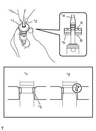
Text in Illustration *1 SST (Guide) *2 SST (Holder) *3 Injector Seal *a Gently Press *b Slowly Slide *c CORRECT *d INCORRECT Using SST (holder), gently press downward on the injector seal (injector connector side). Then slowly slide SST (guide) toward the injector tip to settle the seal into the injector groove.
- SST
- 09260-39021 ( 09261-03011, 09261-03020 )
Note
Be careful that the seal is not pinched between SST (guide) and the injector groove. Replace the seal if it becomes damaged.
Tech Tips
-
When using SST (guide) to settle the seal into the groove, SST (guide) only needs to be slid upward to the position labeled A in the illustration.
-
After using SST (guide) to settle the seal into the groove, return SST (guide) to its position labeled B in the illustration.
-
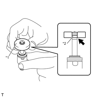
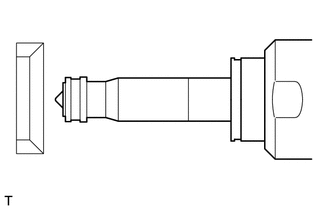
Text in Illustration *1 SST (Guide) *2 Injector Seal Slowly slide SST (guide) toward the tip of the injector. When the injector contact surface of SST (guide) aligns with the seal (injector connector side) as shown in the illustration, hold the position for 5 seconds or more to fully align the seal into the injector groove.
- SST
- 09260-39021 ( 09261-03020 )
Note
Be careful that the seal is not pinched between SST (guide) and the injector groove. Replace the seal if it becomes damaged.
Tech Tips
-
Set SST (guide) so that its bottom surface and seal are flush.
-
If there is difficulty in sliding SST upward, slowly wiggle it from side to side while sliding it up the injector little by little.
-
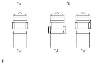
Text in Illustration *a CORRECT *b INCORRECT *c Normal *d Protruding *e Deformed After installing the seals, check that they are not scratched, deformed or protruding from the injector groove.
Note
If a seal is scratched, deformed or protruding from the groove, replace it with a new one.
-
-
INSTALL FUEL INJECTOR ASSEMBLY
Note
If the tip of the fuel injector assembly is struck or the fuel injector assembly is dropped, replace the fuel injector assembly with a new one.
-
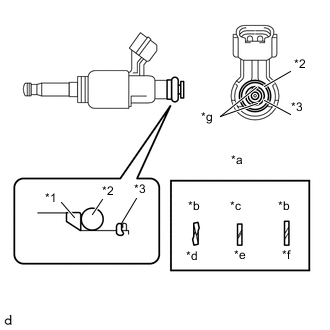
Text in Illustration *1 No. 1 Fuel Injector Backup Ring *2 Fuel Injector Seal *3 No. 2 Fuel Injector Backup Ring *a Alignment Opening *b INCORRECT *c CORRECT *d Overlapped *e Normal *f Stretched *g Grooved Section Install new fuel injector backup rings (No. 1 and No. 2) and a new fuel injector seal to the fuel injector assembly as shown in the illustration.
Note
-
Check that there is no foreign matter or damaged areas in the injector seal groove.
-
Check that the No. 1 fuel injector backup ring is installed in the correct direction.
-
Install the No. 2 fuel injector backup ring so that the grooved section faces the fuel delivery pipe.
-
Make sure that the backup rings and injector seal are installed in the correct order.
-
Check that the alignment openings of the backup rings are not overlapped or stretched as shown in the illustration.
-
After installing the injector seal, check that it is not contaminated with foreign matter and is not damaged.
-
-
Install a new fuel injector insulator to the fuel injector.
Text in Illustration *1 Fuel Injector Insulator Note
Install a new fuel injector insulator to the fuel injector as shown in the illustration.
-
Install the No. 1 injector holder.
-
Text in Illustration *a Protruding section *b Baffle hole 
No gap 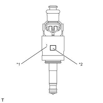
Text in Illustration *1 Number *2 Quick Response Code Apply new engine oil to the surface of the injector insertion hole in the fuel delivery pipe.
Note
-
Check that there are no foreign objects or scratches in the inner face of the fuel injector assembly insertion hole in the fuel delivery pipe.
-
Ensure that gasoline does not adhere to the fuel injector seal or to inside the attachment hole.
-
Insert the fuel injector assembly in a straight line into the fuel delivery pipe without tilting it.
-
Ensure that there is no gap between the No. 1 injector holder and the fuel injector pipe on the high-pressure side.
-
If using a new fuel injector assembly, use one with the same numbers.
Note
-
Make sure that there is no gap between the delivery pipe and the No. 1 injector holder.
-
Check that there is no foreign matter or damage to the injector insertion hole of the delivery pipe.
-
Insert the injector straight into the delivery pipe without tilting it.
-
-
Install the No. 1 injector holder while aligning the protrusion on the No. 1 injector holder with the baffle hole on the fuel delivery pipe.
-
-
INSTALL FUEL DELIVERY PIPE LH
-
Install the fuel delivery pipe LH with the 2 bolts.
- Torque:
- 19 N*m { 194 kgf*cm, 14 ft.*lbf }
-
Connect the 2 fuel injector assembly connectors.
-
-
INSTALL FUEL DELIVERY PIPE RH
-
Install the fuel delivery pipe RH with the 2 bolts.
- Torque:
- 19 N*m { 194 kgf*cm, 14 ft.*lbf }
-
Connect the fuel pressure sensor connector and 2 fuel injector assembly connectors.
-
-
INSTALL FUEL DELIVERY PIPE
-
Temporarily install the new fuel delivery pipe with the 2 union nuts and 3 bolts.
-
Tighten the 3 bolts.
- Torque:
- 6.4 N*m { 65 kgf*cm, 57 in.*lbf }
-
Using a union nut wrench, tighten the 2 union nuts.
- Torque:
- 25 N*m { 255 kgf*cm, 18 ft.*lbf }
-
-
INSTALL NO. 2 FUEL DELIVERY PIPE
-
Temporarily install the new No. 2 fuel pipe with the 2 union nuts.
-
Using a union nut wrench, tighten the 2 union nuts.
- Torque:
- 25 N*m { 255 kgf*cm, 18 ft.*lbf }
-
-
INSTALL INTAKE MANIFOLD