CYLINDER BLOCK REASSEMBLY

PROCEDURE
-
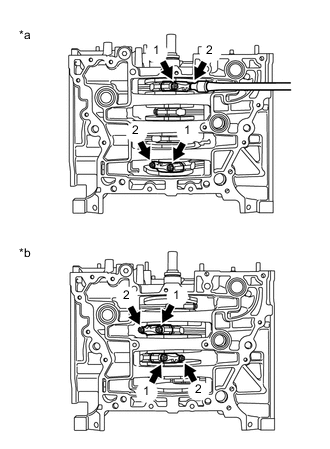
INSTALL NO. 1 CYLINDER BLOCK TIGHT PLUG
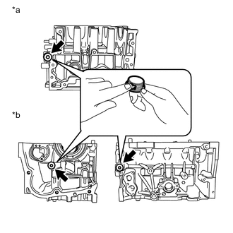
Text in Illustration *a for Bank 1 *b for Bank 2 Note
-
Place wooden blocks wrapped in a cloth under the cylinder block and stabilize the cylinder block during servicing.
-
Place a cloth to avoid scratching the mating surface of the cylinder block during servicing.
-
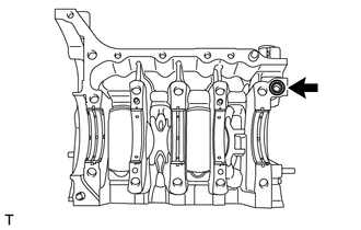
Apply seal packing to the threaded portion of the No. 1 cylinder block tight plugs and install them to the cylinder block (for bank 1) and cylinder block (for bank 2).
Seal packing Three Bond 1105 or equivalent - Torque:
- 37 N*m { 377 kgf*cm, 27 ft.*lbf }
Note
Before applying seal packing, degrease the No. 1 cylinder block tight plugs and thread holes of the cylinder block (for bank 1) and cylinder block (for bank 2).
-
-
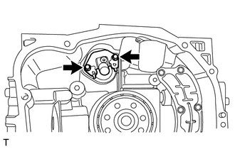
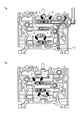
INSTALL CRANKSHAFT SENSOR HOLDER ASSEMBLY
-
Install the crankshaft sensor holder assembly to the cylinder block (for bank 2) with the 2 bolts.
- Torque:
- 6.4 N*m { 65 kgf*cm, 57 in.*lbf }
-
-
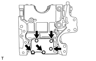
INSTALL CYLINDER BLOCK PLATE
-
Install the cylinder block plate to the cylinder block (for bank 2) with the 5 bolts.
- Torque:
- 6.4 N*m { 65 kgf*cm, 57 in.*lbf }
-
-
INSTALL OIL SEPARATOR COVER
-
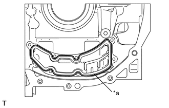
Text in Illustration *a φ3.5 to 5.0 mm (0.138 to 0.197 in.) Using a sealer gun, apply seal packing in a continuous line as shown in the illustration.
Seal packing Three Bond 1217G, 1217H or equivalent Note
-
Clean and degrease the contact surface.
-
Install the oil separator cover within 5 minutes of applying seal packing.
-
-
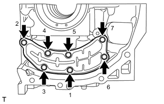
Tight the 7 bolts in the order shown in the illustration to install the oil separator cover to the cylinder block (for bank 1).
- Torque:
- 6.4 N*m { 65 kgf*cm, 57 in.*lbf }
-
-
INSTALL O-RING
-
Attach a new O-ring to the cylinder block (for bank 2).
-
-
INSTALL CRANKSHAFT BEARING
-
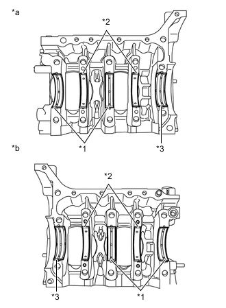
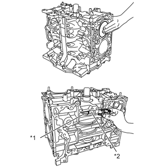
Text in Illustration *1 No. 1 and No. 3 Bearings (with groove) *2 No. 2 and No. 4 Bearings (without groove) *3 No. 5 Bearing *a for Bank 1 *b for Bank 2 Apply engine oil to the crankshaft bearing, and install them to the cylinder block (for bank 1) and cylinder block (for bank 2).
Note
-
Place a cloth to avoid scratching the mating surface of the cylinder block during servicing.
-
The shapes of the No. 1 and No. 3 bearings are different from those of the No. 2 and No. 4 bearings. Be sure to install them in the right locations.
-
-
-
INSTALL CRANKSHAFT
-
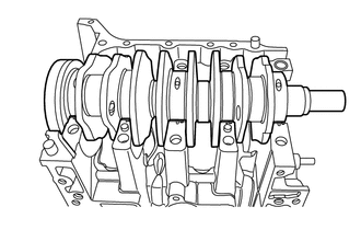
Apply engine oil to the crankshaft journals and place the crankshaft on the cylinder block (for bank 2).
-
-
INSTALL CYLINDER BLOCK SUB-ASSEMBLY (for Bank 1)
-
Using a sealer gun, apply seal packing to the mating surface of the cylinder block sub-assembly (for bank 1) as shown in the illustration.
Seal packing Three Bond 1217G, 1217H or equivalent 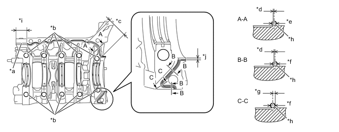
Text in Illustration *a φ3.5 to 4.5 mm (0.138 to 0.177 in.) *b φ0.5to 1.5 mm (0.0197 to 0.0591 in.) *c Range of A-A *d Within φ1.0 mm (0.039 in.) *e φ2.7 to 3.7 mm (0.106 to 0.146 in.) *f φ3.5 to 4.5 mm (0.138 to 0.177 in.) *g φ2.0 mm (0.079 in.) *h Chamfer edge *i 36.0 mm (1.417 in.) *j 2.5 mm (0.098 in.) Note
-
Do not let the seal packing overflow to the oil passage or crankshaft bearing because engine seizure may result.
-
Clean and degrease the contact surface.
-
Install the cylinder block sub-assembly (for bank 1) within 5 minutes of applying seal packing.
-
-
Place the cylinder block sub-assembly (for bank 1) to the cylinder block sub-assembly (for bank 2).
-
Apply engine oil to the washers and cylinder block bolt threads.
Note
To prevent engine oil from entering into the water jacket, do not apply a large amount.
-
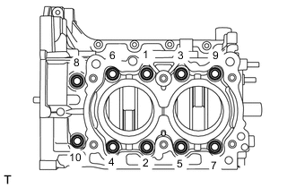
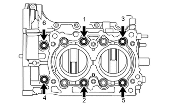
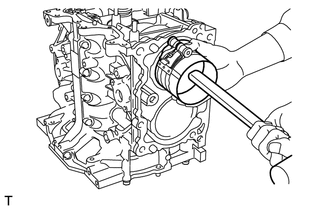
Using a 12 mm socket wrench, tighten the 10 bolts in the order shown in the illustration.
- Torque:
- 35 N*m { 357 kgf*cm, 26 ft.*lbf }
Note
When tightening the bolts, hold the cylinder block sub-assembly (for bank 2) while not holding the cylinder block sub-assembly (for bank 1) to ensure the joint accuracy of the cylinder blocks.
-
Using a 12 mm socket wrench, loosen the 10 bolts by 180 ° in the order shown in the illustration.
Note
When loosening the bolts, hold the cylinder block sub-assembly (for bank 2) while not holding the cylinder block sub-assembly (for bank 1) to ensure the joint accuracy of the cylinder blocks.
-
Using a 12 mm socket wrench, tighten the 10 bolts in the order shown in the illustration.
- Torque:
- 35 N*m { 357 kgf*cm, 26 ft.*lbf }
Note
When tightening the bolts, hold the cylinder block sub-assembly (for bank 2) while not holding the cylinder block sub-assembly (for bank 1) to ensure the joint accuracy of the cylinder blocks.
-

Using a 12 mm socket wrench, loosen the 4 bolts by 180 ° in the order shown in the illustration.
Note
When loosening the bolts, hold the cylinder block sub-assembly (for bank 2) while not holding the cylinder block sub-assembly (for bank 1) to ensure the joint accuracy of the cylinder blocks.
-
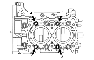
Using a 12 mm socket wrench, tighten the 4 bolts in the order shown in the illustration.
- Torque:
- 17 N*m { 173 kgf*cm, 13 ft.*lbf }
Note
When tightening the bolts, hold the cylinder block sub-assembly (for bank 2) while not holding the cylinder block sub-assembly (for bank 1) to ensure the joint accuracy of the cylinder blocks.
-
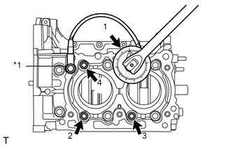
Text in Illustration *1 Temporary Bolt Using a 12 mm socket wrench and an angle gauge, tighten the 4 bolts by additional 60° in the order shown in the illustration.
Note
When tightening the bolts, hold the cylinder block sub-assembly (for bank 2) while not holding the cylinder block sub-assembly (for bank 1) to ensure the joint accuracy of the cylinder blocks.
Tech Tips
Temporarily install the appropriate bolt for the angle gauge if necessary.
-

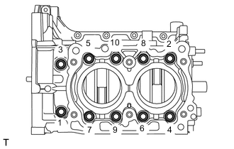
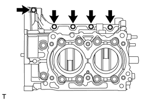
Using a 12 mm socket wrench, loosen the 6 bolts by 180 ° in the order shown in the illustration.
Note
When loosening the bolts, hold the cylinder block sub-assembly (for bank 2) while not holding the cylinder block sub-assembly (for bank 1) to ensure the joint accuracy of the cylinder blocks.
-
Using a 12 mm socket wrench, tighten the 6 bolts in the order shown in the illustration.
- Torque:
- 17 N*m { 173 kgf*cm, 13 ft.*lbf }
Note
When tightening the bolts, hold the cylinder block sub-assembly (for bank 2) while not holding the cylinder block sub-assembly (for bank 1) to ensure the joint accuracy of the cylinder blocks.
-
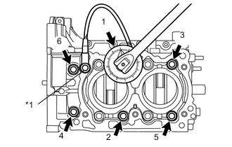
Text in Illustration *1 Temporary Bolt Using a 12 mm socket wrench and an angle gauge, tighten the 6 bolts by additional 60° in the order shown in the illustration.
Note
When tightening the bolts, hold the cylinder block sub-assembly (for bank 2) while not holding the cylinder block sub-assembly (for bank 1) to ensure the joint accuracy of the cylinder blocks.
Tech Tips
Temporarily install the appropriate bolt for the angle gauge if necessary.
-
Tighten the 5 bolts.
- Torque:
- 25 N*m { 255 kgf*cm, 18 ft.*lbf }
Tech Tips
After tightening, if the seal packing is squeezed out in the seal surface area of the chain cover and oil pan sub-assembly, completely remove it. Seal packing on the chamfer area, however, should not be removed.
-
-
INSTALL REAR ENGINE OIL SEAL
-
Apply a light coat of engine oil to a new rear engine oil seal inner periphery and outer periphery.
-
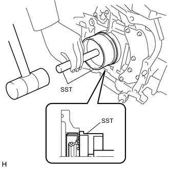
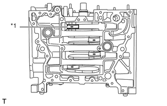
Using SST and a hammer, tap in the rear engine oil seal uniformly to the position shown in the illustration.
- SST
- 09223-15030
- 09950-70010 ( 09951-07150 )
Oil seal tap-in depth 0 to 1.0 mm (0 to 0.039 in.) from the cylinder block surface Note
-
Do not tap in the rear engine oil seal at an angle.
-
Remove the engine oil from the crankshaft.
-
Do not tap in the rear engine oil seal more than necessary.
-
-
INSTALL CYLINDER BLOCK SUB-ASSEMBLY
-
Mount the cylinder block sub-assembly onto an engine stand.
-
-
INSTALL PISTON WITH PIN SUB-ASSEMBLY
-
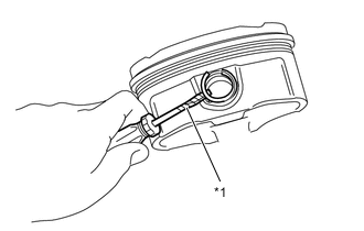
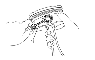
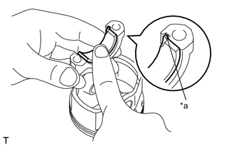
Using a screwdriver with its tip wrapped in protective tape, install the piston pin hole snap ring on one end of the piston.
Text in Illustration *1 Protective Tape Tech Tips
-
Make sure that the piston pin hole snap ring is firmly attached into the piston pin hole snap ring groove.
-
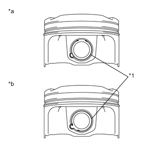
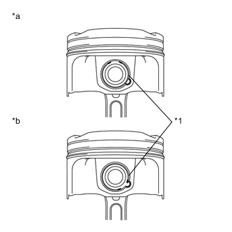
After installing the piston pin hole snap ring, rotate the piston pin hole snap ring so that its end part and the cutout portion of the piston pin hole snap ring groove do not match.
Text in Illustration *1 Piston Pin Hole Snap Ring *a Correct *b Incorrect -
-
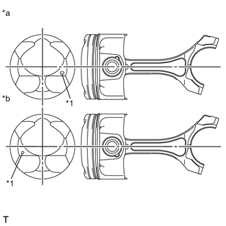
Text in Illustration *1 Front Mark *a for Bank 1 *b for Bank 2 Set the piston to the connecting rod.
Tech Tips
Align the front mark of the piston and the direction of the connecting rod correctly as shown in the illustration.
-
Apply engine oil to the piston pin and install it to the piston.
-
Using a screwdriver with its tip wrapped in protective tape, install the piston pin hole snap ring to the piston.
Text in Illustration *1 Protective Tape Tech Tips
-
Make sure the piston pin hole snap ring is firmly attached into the piston pin hole snap ring groove.
-
After installing the piston pin hole snap ring, rotate the piston pin hole snap ring so that its end part and the cutout portion of the piston pin hole snap ring groove do not match.
Text in Illustration *1 Piston Pin Hole Snap Ring *a Correct *b Incorrect -
-
-
INSTALL PISTON RING SET
-
Install the oil ring expander, lower oil ring side rail and upper oil ring side rail in order by hand.
Tech Tips
The oil ring consists of the 2 oil ring side rails and oil ring expander.
-
Set the oil ring expander ends at the location B in the illustration.
-
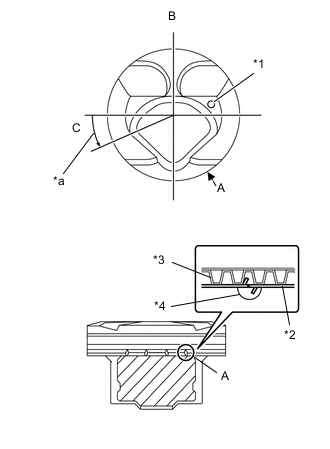
Hook the stoppers at the rail ends of the lower oil ring side rail into cutout A of the piston and the oil ring expander as shown in the illustration.
-
Align the rail ends of the upper oil ring side rail within the range C and hook the stopper into the oil ring expander.
-
Using a piston ring expander, install the No. 2 compression ring and No. 1 compression ring in order.
Text in Illustration *1 Front Mark *2 Lower Oil Ring Side Rail *3 Expander *4 Cutout *a 0 to 20° -
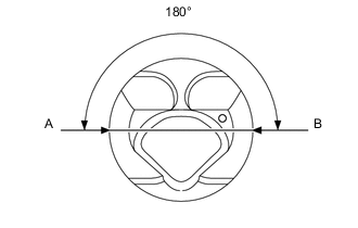
Set the No. 1 compression ring ends at the location A or B in the illustration.
Tech Tips
The No. 1 compression ring ends can be set either at A or B.
-
Set the No. 2 compression ring ends at the location A or B, that is 180° opposite of those of the No. 1 compression ring.
-
Check that the piston rings and oil rings are correctly set.
-
-
INSTALL PISTON SUB-ASSEMBLY WITH CONNECTING ROD
-
Operate the engine stand so that the oil pan side faces upward.
-
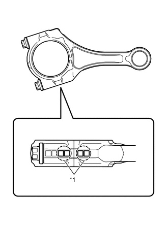
Text in Illustration *a Claw Install the connecting rod bearings to the connecting rod and connecting rod cap. <*1>
-
Check that the piston rings and oil rings are correctly set.
-
Apply engine oil to the piston and inside the cylinder bore.
-
Text in Illustration *1 Crank Pin Turn the crankshaft so that the crank pin is positioned at TDC.
-
Text in Illustration *1 Connecting Rod *2 Crankshaft Pin Using a piston ring compressor, compress the piston rings and insert the piston with connecting rod into the cylinder block.
Note
-
When inserting the piston with connecting rod, be careful not to scratch the cylinder bore or crank pin by connecting the rod edge.
-
Be careful not to apply too much impact when inserting to prevent the connecting rod bearing from falling off.
Tech Tips
Face the front mark toward the front of the engine.
-
-
Apply engine oil to the seating face of the connecting rod cap and threads of the connecting rod cap bolts.
-
Text in Illustration *1 Matching Symbol While pushing the piston top, turn the crankshaft to position the crankshaft pin and connecting rod large end as shown in the illustration, and then attach the connecting rod cup with 2 new connecting rod cap bolts.
Tech Tips
-
Each connecting rod has its own mating cap. Make sure that they are assembled correctly by checking their matching symbols.
-
Use new connecting rod cap bolts.
-
Turn the crankshaft counterclockwise when installing the No. 1 or No. 3 piston with connecting rod, and turn the crankshaft clockwise when installing the No. 2 or No. 4 piston with connecting rod.
-
-
Text in Illustration *a No. 1 and No. 4 *b No. 2 and No. 3 Using a "TORX" socket wrench E14, tighten the 2 connecting rod cup bolts in the order shown in the illustration.
- Torque:
- 10 N*m { 102 kgf*cm, 7 ft.*lbf }
-
Retighten the 2 connecting rod cup bolts in the same order as above. <*2>
- Torque:
- 25 N*m { 255 kgf*cm, 18 ft.*lbf }
-
In the same procedures from <*1> to <*2>, install the No. 2, No. 3 and No. 4 piston with connecting rods.
-
Text in Illustration *1 Temporary Bolt *a No. 1 and No. 4 *b No. 2 and No. 3 Using a "TORX" socket wrench E14 and an angle gauge, tighten the connecting rod cup bolts for the No. 1 to No. 4 piston with connecting rods by additional 92.5°.
Tech Tips
Temporarily install the appropriate bolt for the angle gauge if necessary.
-
Check that the crankshaft can be turned smoothly.
-