ENGINE UNIT INSTALLATION

PROCEDURE
-
INSTALL IGNITION COIL ASSEMBLY
-
Install the 4 ignition coils with the 4 bolts.
- Torque:
- 8.5 N*m { 87 kgf*cm, 75 in.*lbf }
-
-
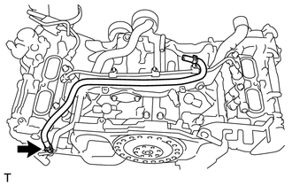
INSTALL NO. 1 WATER BY-PASS PIPE (for Manual Transmission)
-
Install the No. 1 water by-pass pipe with the 2 bolts.
- Torque:
- 6.4 N*m { 65 kgf*cm, 57 in.*lbf }
-
Connect the water by-pass hose with the hose clamp.
-
-
INSTALL NO. 1 WATER BY-PASS PIPE (for Automatic Transmission)
-
Install the No. 1 water by-pass pipe with the 2 bolts.
- Torque:
- 6.4 N*m { 65 kgf*cm, 57 in.*lbf }
-
Connect the 2 water by-pass hoses with the 2 hose clamps.
-
-
CONNECT NO. 3 TRANSMISSION OIL COOLER HOSE (for Automatic Transmission)
-
Connect the No. 3 transmission oil cooler hose with the hose clamp.
-
-
INSTALL NO. 2 WATER BY-PASS HOSE
-
Connect the No. 2 water by-pass hose with the clamp.
-
-
CONNECT NO. 2 VENTILATION HOSE
-
Connect the No. 2 ventilation hose.
-
-
INSTALL ENGINE WIRE
-
Connect the ground wire with the 2 bolts.
- Torque:
- 19 N*m { 194 kgf*cm, 14 ft.*lbf }
-
Connect each connector and each clamp to fix the engine wire as shown in the illustration, and check that the engine wire is correctly installed.
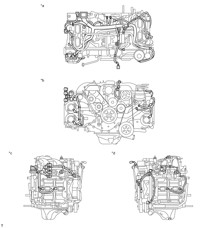
Text in Illustration *a Upper side *b Front side *c Right side *d Left side
-
-
INSTALL PUMP DRIVE CASE ASSEMBLY
-
INSTALL VALVE LIFTER
-
INSTALL FUEL PUMP ASSEMBLY
-
INSTALL FUEL INJECTOR O-RING
-
INSTALL FUEL INJECTOR ASSEMBLY
-
INSTALL FUEL DELIVERY PIPE LH
-
INSTALL FUEL DELIVERY PIPE RH
-
INSTALL FUEL DELIVERY PIPE
-
INSTALL NO. 2 FUEL DELIVERY PIPE
-
INSTALL INTAKE MANIFOLD
-
Install 2 new gaskets to the intake manifold.
-
Install the intake manifold with the 6 bolts.
- Torque:
- 25 N*m { 255 kgf*cm, 18 ft.*lbf }
-
Engage the 2 clamps and connect the 4 connectors.
-
Connect the fuel pump connector.
-
Connect the No. 1 vacuum switching valve assembly connector.
-
Connect the vacuum sensor connector.
-
Connect the 2 water by-pass hoses to the throttle body assembly.
-
Connect the throttle body assembly connector.
-
-
CONNECT VENTILATION HOSE
-
INSTALL FUEL DELIVERY PIPE SUB-ASSEMBLY
-
Install the fuel delivery pipe sub-assembly to the fuel pump assembly with a new gasket and the union bolt.
- Torque:
- 31 N*m { 316 kgf*cm, 23 ft.*lbf }
-
Connect the No. 2 fuel vapor feed hose.
-
Install the bolt and connect the fuel delivery pipe sub-assembly.
- Torque:
- 6.4 N*m { 65 kgf*cm, 57 in.*lbf }
-
-
INSTALL INJECTOR COVER (for Bank 2)
-
Install the injector cover to the intake manifold with the 2 bolts.
- Torque:
- 19 N*m { 194 kgf*cm, 14 ft.*lbf }
-
-
INSTALL INJECTOR COVER (for Bank 1)
-
Install the injector cover to the intake manifold with the 2 bolts.
- Torque:
- 19 N*m { 194 kgf*cm, 14 ft.*lbf }
-
-
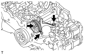
INSTALL IDLER PULLEY BRACKET (w/o Air Conditioning System)
-
Temporarily tighten the idler pulley bracket with the 3 bolts.
-
Fully tighten the 3 bolts shown in the illustration.
- Torque:
- 36 N*m { 367 kgf*cm, 27 ft.*lbf }
-
-
INSTALL COMPRESSOR WITH MAGNET CLUTCH (w/ Air Conditioning System)
-
INSTALL V-RIBBED BELT TENSIONER ASSEMBLY
-
INSTALL NO. 2 IDLER PULLEY SUB-ASSEMBLY
-
INSTALL OIL LEVEL DIPSTICK GUIDE
-
INSTALL GENERATOR ASSEMBLY
-
Install the generator assembly with the 2 bolts.
- Torque:
- 25 N*m { 255 kgf*cm, 18 ft.*lbf }
-
-
INSTALL FAN AND GENERATOR V BELT
-
INSTALL BELT GENERATOR COVER
-
INSTALL GENERATOR COVER