ENGINE UNIT REASSEMBLY

PROCEDURE
-
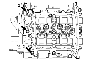
INSTALL OIL SPACER LH
-
Install the oil spacer LH with the 2 bolts.
- Torque:
- 6.4 N*m { 65 kgf*cm, 57 in.*lbf }
-
-
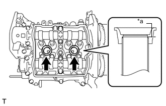
INSTALL OIL CONTROL VALVE FILTER (for Bank 2)
-
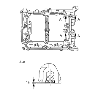
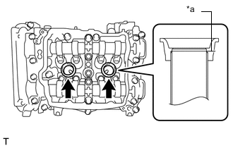
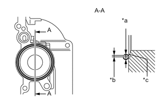
Text in Illustration *a 0 to 0.5 mm (0 to 0.0197 in.) from the face of the camshaft housing sub-assembly LH Install 2 new oil control valve filters to the camshaft housing sub-assembly LH as shown in the illustration.
-
-
INSTALL CAMSHAFT (for Bank 2)
-
INSTALL CAMSHAFT CAP (for Bank 2)
-
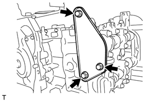
INSTALL HOLE PLUG (for Manual Transmission)
-
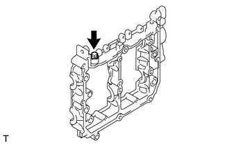
Install a new gasket and the hole plug to the camshaft housing sub-assembly RH.
- Torque:
- 25 N*m { 255 kgf*cm, 18 ft.*lbf }
-
-
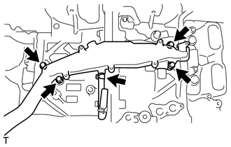
INSTALL CAMSHAFT OIL FEED PIPE SUB-ASSEMBLY (for Automatic Transmission)
-
Temporarily install 2 new gaskets and the camshaft oil feed pipe sub-assembly with the bolt and 2 union bolts.
-
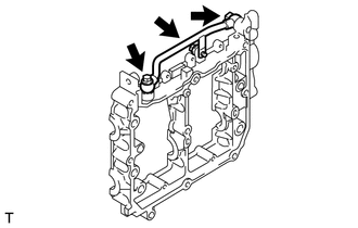
Tighten the 2 union bolts to the specified torque.
- Torque:
- 31 N*m { 316 kgf*cm, 23 ft.*lbf }
-
Tighten the bolt to the specified torque.
- Torque:
- 6.4 N*m { 65 kgf*cm, 57 in.*lbf }
-
-
INSTALL OIL SPACER RH
-
Install the oil spacer RH with the 2 bolts.
- Torque:
- 6.4 N*m { 65 kgf*cm, 57 in.*lbf }
-
-
INSTALL OIL CONTROL VALVE FILTER (for Bank 1)
-
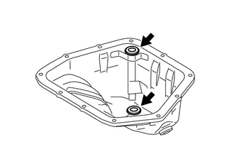
Text in Illustration *a 0 to 0.5 mm (0 to 0.0197 in.) from the face of the camshaft housing sub-assembly RH Install 2 new oil control valve filters to the camshaft housing sub-assembly RH as shown in the illustration.
-
-
INSTALL CAMSHAFT (for Bank 1)
-
INSTALL CAMSHAFT CAP (for Bank 1)
-
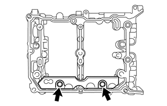
INSTALL OIL PAN SUB-ASSEMBLY
-
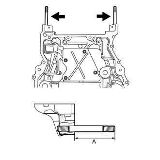
Install the 2 stud bolts to the oil pan sub-assembly.
- Torque:
- 10 N*m { 102 kgf*cm, 7 ft.*lbf }
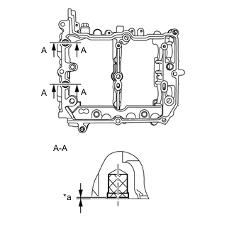
Standard height (A) 70.0 mm (2.756 in.) -
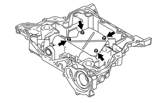
Install the baffle plate to the oil pan sub-assembly with the 4 bolts.
- Torque:
- 6.4 N*m { 65 kgf*cm, 57 in.*lbf }
-
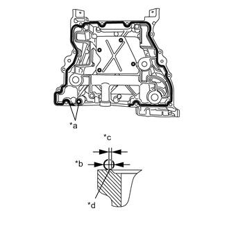
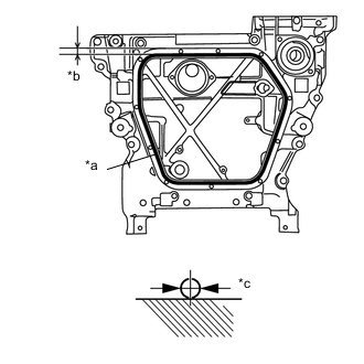
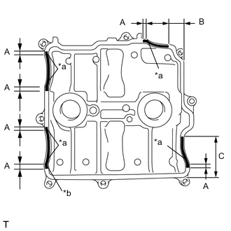
Text in Illustration *a Seal Packing *b φ4.0 to 6.0 mm (0.158 to 0.236 in.) *c 1.5 mm (0.059 in.) *d Chamfer edge Using a sealer gun, apply seal packing in a continuous line as shown in the illustration.
Seal packing Three Bond 1217G, 1217H or equivalent Note
-
Clean and degrease the contact surface.
-
Install the oil pan sub-assembly within 5 minutes of applying seal packing.
-
Apply seal packing 1.5 mm (0.0591 in.) away from the outer side of the chamfer edge. However, it is allowed to apply the seal packing on the chamfer around the bolt hole.
-
-
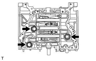
Install 3 new O-rings to the cylinder block.
-
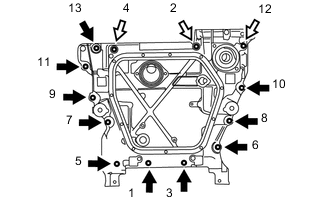
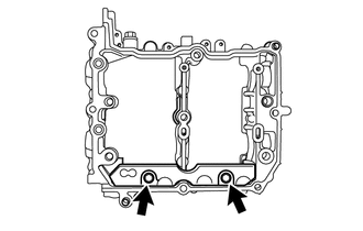
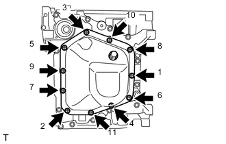
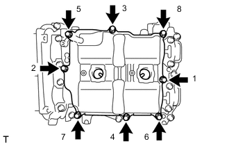
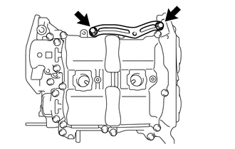
Tighten the 13 bolts in the order shown in the illustration to install the oil pan sub-assembly to the cylinder block.
- Torque:
- 18 N*m { 184 kgf*cm, 13 ft.*lbf }
Text in Illustration 
Bolt A 
Bolt B Length of bolt A 25.0 mm (0.984 in.) Length of bolt B 75.0 mm (2.953 in.) Tech Tips
After tightening the bolts, if the seal packing is squeezed out onto the seal surface of the chain cover, completely remove it.
-
-
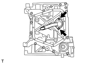
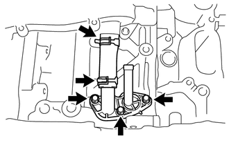
INSTALL OIL STRAINER SUB-ASSEMBLY
-
Install a new O-ring.
-
Install the oil strainer sub-assembly to the oil pan sub-assembly with the 2 bolts.
- Torque:
- 6.4 N*m { 65 kgf*cm, 57 in.*lbf }
-
-
INSTALL NO. 2 OIL PAN SUB-ASSEMBLY
-
Install 2 new oil pan seal rings to the No. 2 oil pan sub-assembly.
-
Text in Illustration *a Seal Packing *b 9.5 mm (0.374 in.) *c φ4.0 to 6.0 mm (0.158 to 0.236 in.) Using a sealer gun, apply seal packing in a continuous line as shown in the illustration.
Seal packing Three Bond 1217G, 1217H or equivalent Note
-
Clean and degrease the contact surface.
-
Install the No. 2 oil pan sub-assembly within 5 minutes of applying seal packing.
-
-
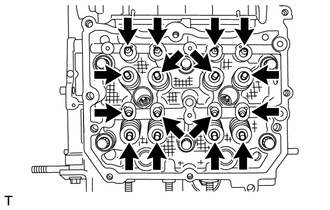
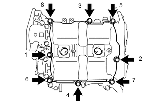
Tighten the 11 bolts in the order shown in the illustration to install the No. 2 oil pan sub-assembly.
- Torque:
- 6.4 N*m { 65 kgf*cm, 57 in.*lbf }
-
Install a new gasket and the drain plug.
- Torque:
- 42 N*m { 425 kgf*cm, 31 ft.*lbf }
-
-
INSTALL NO. 2 ENGINE HANGER
-
Install the No. 2 engine hanger to the cylinder block (for bank 1) with the 2 bolts.
- Torque:
- 21 N*m { 214 kgf*cm, 16 ft.*lbf }
-
-
INSTALL NO. 2 CYLINDER HEAD GASKET
-
INSTALL CYLINDER HEAD SUB-ASSEMBLY LH
-
INSTALL CAMSHAFT HOUSING SUB-ASSEMBLY LH
-
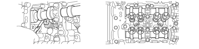
Apply engine oil to the 8 valve adjusting shims and 8 roller rocker arm pivots, and then install them to the cylinder head sub-assembly LH.
Tech Tips
Be sure to install the removed parts in their original locations.
-
Apply engine oil to 2 new O-rings and the 8 No. 1 valve rocker arm sub-assemblies, and then install them to the cylinder head sub-assembly LH.
-
Using a sealer gun, apply seal packing in a continuous line as shown in the illustration.
Seal packing Three Bond 1217G, 1217H or equivalent 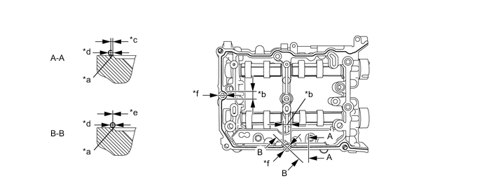
Text in Illustration *a Chamfer edge *b Range of B-B *c within 1.0 mm (0.0394 in.) *d φ2.5 to 3.5 mm (0.098 to 0.138 in.) *e -0.5 to 0.5 mm (-0.0197 to 0.0197 in.) *f 18.0 mm (0.709 in.) Note
-
Clean and degrease the contact surface.
-
Do not apply excessive seal packing.
-
Install the camshaft housing sub-assembly LH within 5 minutes of applying seal packing.
-
After tightening the bolts, if the seal packing is squeezed out onto the seal surface of the chain cover, completely remove it.
-
-
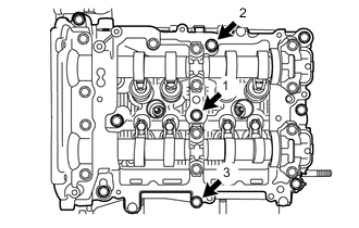
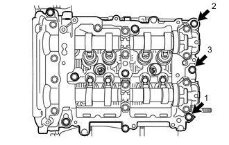
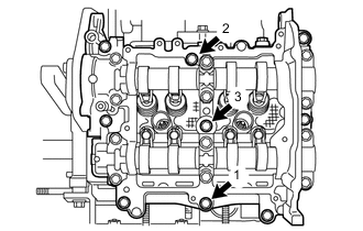
Tighten the 9 bolts in the order shown in the illustration to install the camshaft housing sub-assembly LH.
- Torque:
- 18 N*m { 184 kgf*cm, 13 ft.*lbf }
Tech Tips
Set the intake camshaft LH and the exhaust camshaft LH to the zero-lift position.
-

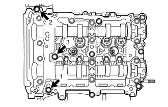
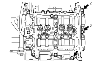
Loosen the 3 bolts by 180° in the order shown in the illustration.
-
Tighten the 3 bolts in the order shown in the illustration.
- Torque:
- 18 N*m { 184 kgf*cm, 13 ft.*lbf }
-
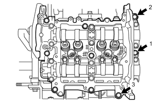
Loosen the 3 bolts by 180° in the order shown in the illustration.
-
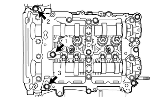
Tighten the 3 bolts in the order shown in the illustration.
- Torque:
- 18 N*m { 184 kgf*cm, 13 ft.*lbf }
-
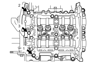
Loosen the 3 bolts by 180° in the order shown in the illustration.
-
Tighten the 3 bolts in the order shown in the illustration.
- Torque:
- 18 N*m { 184 kgf*cm, 13 ft.*lbf }
Tech Tips
After tightening the bolts, if the seal packing is squeezed out onto the seal surface of the chain cover, completely remove it.
-
-
INSPECT VALVE CLEARANCE (for Bank 2)
Note
With the chain sub-assembly (for bank 2) removed, valve heads may contact each other if the camshafts are turned, causing the valve stems to bend. To avoid this, do not turn the intake camshaft LH and exhaust camshaft LH more than the zero-lift rang (The range where the camshafts can be turned lightly by hand).
-
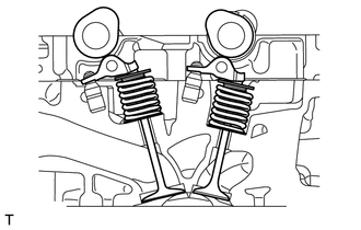
Using a feeler gauge, check the valve clearance between the cam base circle and the roller surface of the No. 1 valve rocker arm sub-assembly.
Standard valve clearance (cold) 0.10 to 0.15 mm (0.00394 to 0.00591 in.) for intake 0.20 to 0.24 mm (0.00787 to 0.00945 in.) for exhaust Tech Tips
-
Set the intake camshaft LH and the exhaust camshaft LH to the zero-lift position.
-
If the clearance is not as specified, take notes of the value in order to adjust the valve clearance later on.
-
-
-
ADJUST VALVE CLEARANCE (for Bank 2)
-
Remove the camshaft housing sub-assembly LH.
-
Remove the No. 1 valve rocker arm sub-assemblies.
-
Remove the valve adjusting shims.
-
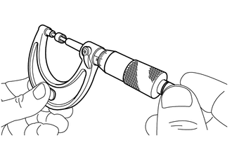
Using a micrometer, measure the thickness of the valve adjusting shims.
-
Calculate the thickness of the valve adjusting shim so that the valve clearance comes within the specified values.
Intake side A = B + (C - 0.13 mm (0.00512 in.) x 1.54 Exhaust side A = B + (C - 0.22 mm (0.00866 in.) x 1.69 A Required valve adjusting shim thickness B Removed valve adjusting shim thickness C Measured valve clearance -
Apply engine oil to the inner face of the valve adjusting shims and install them to the valves.
Note
Check if the shims can be rotated smoothly on the valves.
-
Install the No. 1 valve rocker arm sub-assemblies.
-
Install the camshaft housing sub-assembly LH.
-
-
INSTALL CYLINDER HEAD COVER SUB-ASSEMBLY LH
-
Text in Illustration *a Spark plug tube edge Apply a light layer of engine oil to 2 new spark plug tube gaskets and install them to the spark plug tubes as shown in the illustration.
-
Install a new cylinder head cover gasket to the cylinder head cover sub-assembly LH.
-
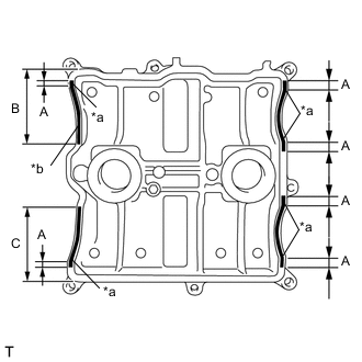
Text in Illustration *a Arch starting point *b φ2,0 to 4.0 mm (0.079 to 0.158 in.) Using a sealer gun, apply seal packing to the mating surface of cylinder head cover sub-assembly LH as shown in the illustration.
Seal packing Three Bond 1217G, 1217H or equivalent Area Application Length A 10.0 mm (0.394 in.) or more B 18.8 mm (0.740 in.) or more C 63.0 mm (2.480 in.) or more -
Tighten the 8 bolts in the order shown in the illustration and install the cylinder head cover sub-assembly LH.
- Torque:
- 6.4 N*m { 65 kgf*cm, 57 in.*lbf }
-
-
INSTALL CYLINDER HEAD GASKET
-
INSTALL CYLINDER HEAD SUB-ASSEMBLY RH
-
INSTALL CAMSHAFT HOUSING SUB-ASSEMBLY RH
-
Apply engine oil to the 8 valve adjusting shims and 8 roller rocker arm pivots, and then install them to the cylinder head sub-assembly.
Tech Tips
Be sure to install the removed parts in their original locations.
-
Apply engine oil to 2 new O-rings and the 8 No. 1 valve rocker arm sub-assemblies, and then install them to the cylinder head sub-assembly.
-
Using a sealer gun, apply seal packing in a continuous line as shown in the illustration.
Seal packing Three Bond 1217G, 1217H or equivalent 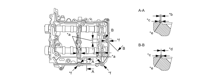
Text in Illustration *a Range of B-B *b 0 to 1.0 mm (0 to 0.0394 in.) *c φ2.5 to 3.5 mm (0.098 to 0.138 in.) *d -0.5 to 0.5 mm (-0.0197 to 0.0197 in.) *e Chamfer edge *f 18.0 mm (0.709 in.) Note
-
Clean and degrease the contact surface.
-
Do not apply excessive seal packing.
-
Install the camshaft housing sub-assembly RH within 5 minutes of applying seal packing.
-
After tightening the bolts, if the seal packing is squeezed out onto the seal surface of the chain cover, completely remove it.
-
-
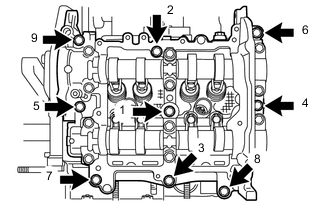
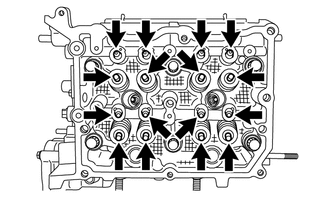
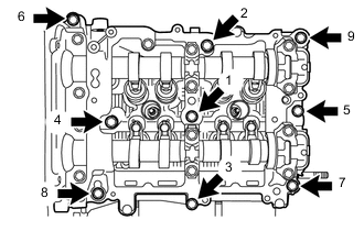
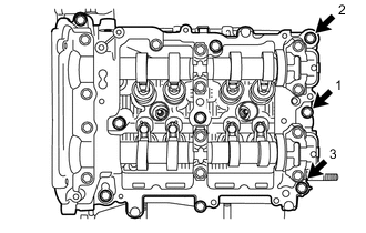
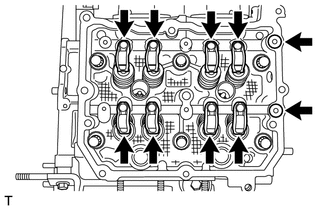
Tighten the 9 bolts in the order shown in the illustration to install the camshaft housing sub-assembly RH.
- Torque:
- 18 N*m { 184 kgf*cm, 13 ft.*lbf }
Tech Tips
Set the intake camshaft RH and the exhaust camshaft RH to the zero-lift position.
-
Loosen the 3 bolts by 180° in the order shown in the illustration.
-

Tighten the 3 bolts in the order shown in the illustration.
- Torque:
- 18 N*m { 184 kgf*cm, 13 ft.*lbf }
-
Loosen the 3 bolts by 180° in the order shown in the illustration.
-
Tighten the 3 bolts in the order shown in the illustration.
- Torque:
- 18 N*m { 184 kgf*cm, 13 ft.*lbf }
-
Loosen the 3 bolts by 180° in the order shown in the illustration.
-
Tighten the 3 bolts in the order shown in the illustration.
- Torque:
- 18 N*m { 184 kgf*cm, 13 ft.*lbf }
Tech Tips
After tightening the bolts, if the seal packing is squeezed out onto the seal surface of the chain cover, completely remove it.
-
-
INSPECT VALVE CLEARANCE (for Bank 1)
Note
With the chain sub-assembly (for bank 1) removed, valve heads may contact each other if the camshafts are turned, causing the valve stems to bend. To avoid this, do not turn the intake camshaft RH and exhaust camshaft RH more than the zero-lift rang (The range where the camshafts can be turned lightly by hand).
-
Using a feeler gauge, check the valve clearance between the cam base circle and the roller surface of the No. 1 valve rocker arm sub-assembly.
Standard valve clearance (cold) 0.10 to 0.15 mm (0.00394 to 0.00591 in.) for intake 0.20 to 0.24 mm (0.00787 to 0.00945 in.) for exhaust Tech Tips
-
Set the intake camshaft RH and the exhaust camshaft RH to the zero-lift position.
-
If the clearance is not as specified, take notes of the value in order to adjust the valve clearance later on.
-
-
-
ADJUST VALVE CLEARANCE (for Bank 1)
-
Remove the camshaft housing sub-assembly RH.
-
Remove the No. 1 valve rocker arm sub-assemblies.
-
Remove the valve adjusting shims.
-
Using a micrometer, measure the thickness of the valve adjusting shims.
-
Calculate the thickness of the valve adjusting shim so that the valve clearance comes within the specified values.
Intake side A = B + (C - 0.13 mm (0.00512 in.) x 1.54 Exhaust side A = B + (C - 0.22 mm (0.00866 in.) x 1.69 A Required valve adjusting shim thickness B Removed valve adjusting shim thickness C Measured valve clearance -
Apply engine oil to the inner face of the valve adjusting shims and install them to the valves.
Note
Check if the shims can be rotated smoothly on the valves.
-
Install the No. 1 valve rocker arm sub-assemblies.
-
Install the camshaft housing sub-assembly RH.
-
-
INSTALL CYLINDER HEAD COVER SUB-ASSEMBLY RH
-
Text in Illustration *a Spark plug tube edge Apply a light layer of engine oil to 2 new spark plug tube gaskets and install them to the spark plug tubes as shown in the illustration.
-
Install a new cylinder head cover gasket to the cylinder head cover sub-assembly RH.
-
Text in Illustration *a Arch starting point *b φ2,0 to 4.0 mm (0.079 to 0.158 in.) Using a sealer gun, apply seal packing to the mating surface of cylinder head cover sub-assembly RH as shown in the illustration.
Seal packing Three Bond 1217G, 1217H or equivalent Area Application Length A 10.0 mm (0.394 in.) or more B 68.0 mm (2.677 in.) or more C 70.7 mm (2.784 in.) or more -
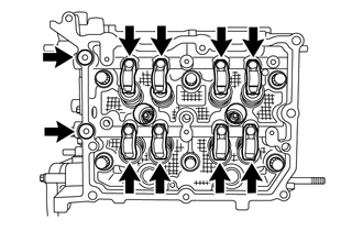
Tighten the 8 bolts in the order shown in the illustration and install the cylinder head cover sub-assembly RH.
- Torque:
- 6.4 N*m { 65 kgf*cm, 57 in.*lbf }
-
-
INSTALL INJECTOR DRIVER BRACKET
-
Install the injector driver bracket with the 2 bolts.
- Torque:
- 6.4 N*m { 65 kgf*cm, 57 in.*lbf }
-
-
INSTALL SPARK PLUG
-
Using a 14 mm spark plug wrench, install the 4 spark plugs.
- Torque:
- 17 N*m { 173 kgf*cm, 13 ft.*lbf }
-
-
INSTALL CAMSHAFT TIMING EXHAUST GEAR ASSEMBLY LH
-
INSTALL CAMSHAFT TIMING INTAKE GEAR ASSEMBLY LH
-
INSTALL CAMSHAFT TIMING EXHAUST GEAR ASSEMBLY RH
-
INSTALL CAMSHAFT TIMING INTAKE GEAR ASSEMBLY RH
-
INSTALL CRANKSHAFT TIMING GEAR OR SPROCKET
-
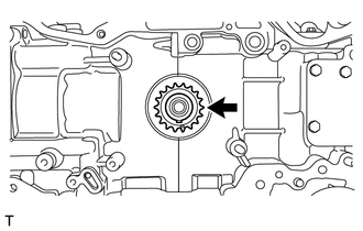
Install the crankshaft timing gear or sprocket.
-
-
INSTALL CHAIN SUB-ASSEMBLY (for Bank 2)
Note
Do not allow any foreign matter to adhere or to enter into the component parts during installation.
Tech Tips
Apply engine oil to all component parts of the chain sub-assembly.
-
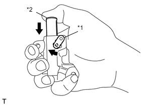
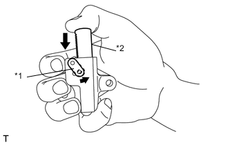
Text in Illustration *1 Link Plate *2 Plunger Move the link plate in the direction of the arrow in the illustration to press in the plunger.
-
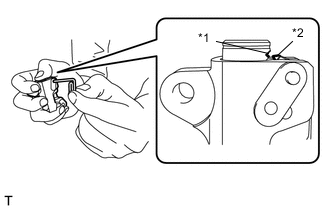
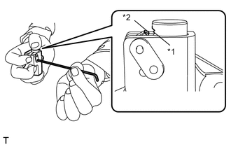
Text in Illustration *1 First notch of the plunger rack *2 Stopper Tooth Insert an approximately 1 mm (0.0394 in.) diameter wire or the like into the chain tensioner assembly through the stopper pin hole, and hold the plunger.
Tech Tips
If the stopper pin hole on the link plate and the stopper pin hole on the chain tensioner assembly are not aligned, check that the first notch of the plunger rack is engaged with the stopper tooth. If not engaged, retract the plunger a little so that the first notch of the plunger rack is engaged with the stopper tooth.
-
Temporarily install the crankshaft pulley spacer and crankshaft pulley.
-
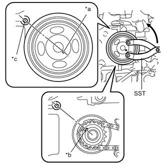
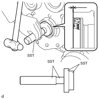
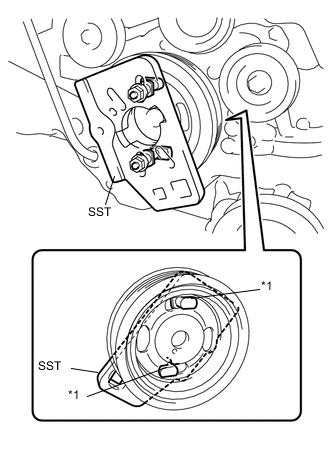
Text in Illustration *a Crankshaft Pulley Pin Hole *b Alignment Mark *c Crankshaft Timing Gear key Using SST, set the crankshaft pulley pin hole at the position shown in the illustration.
- SST
- 09960-10010 ( 09962-01000, 09963-01000 )
Note
Make sure to perform this operation to prevent the valves and pistons from contacting each other.
Tech Tips
At this time, the alignment mark on the crankshaft timing gear or sprocket and the crankshaft timing gear key are at the positions shown in the illustration.
-
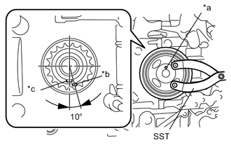
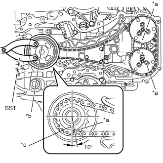
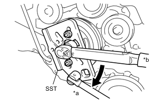
Text in Illustration *a Alignment Mark *b 25°to 30° Using SST, turn the camshaft timing intake gear assembly LH and align the alignment mark as shown in the illustration.
- SST
- 09960-10010 ( 09962-01000, 09963-00700 )
Note
Do not turn the exhaust camshaft LH. If the exhaust camshaft LH is turned, valve heads may come into contact with each other, causing the valve stems to bend.
-
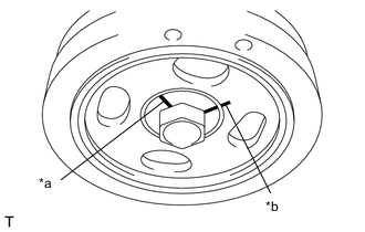
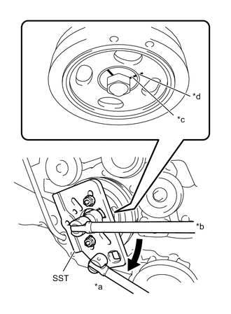
Text in Illustration *a Crankshaft Pulley Pin Hole *b Crankshaft Timing Gear key *c Cylinder Block Guide Pin Using SST, turn the crankshaft about 200 degrees counterclockwise until the crankshaft pulley pin hole is aligned at the position shown in the illustration.
- SST
- 09960-10010 ( 09962-01000, 09963-01000 )
Note
Never turn the crankshaft clockwise because the valves may come into contact with the piston. Turning the crankshaft clockwise is only allowed when adjusting the key position precisely.
Tech Tips
At this time, the crankshaft timing gear key is at the position shown in the illustration.
-
Remove the crankshaft pulley and crankshaft pulley spacer.
-
Text in Illustration *a Alignment Mark *b 25° to 30° Align the alignment mark on the camshaft timing exhaust gear assembly LH as shown in the illustration.
Note
To avoid damaging the valves, do not turn the camshaft timing exhaust gear assembly LH more than the zero-lift range (The range where camshaft timing exhaust gear assembly LH can be turned lightly by hand).
-
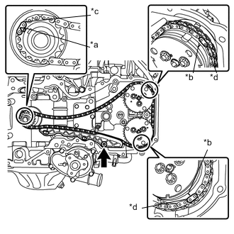
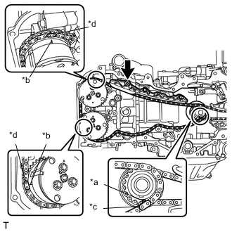
Text in Illustration *a Alignment Mark (Oval) *b Alignment Mark (Engraved Line) *c Mark plate (Grayish Blue) *d Mark plate (Pink) Install the chain sub-assembly in the following order.
-
Align the mark plate (grayish blue) on the chain sub-assembly with the alignment mark (oval) on the crankshaft timing gear or sprocket.
-
Align the mark plate (pink) on the chain sub-assembly with the alignment mark (engraved line) on the camshaft timing exhaust gear assembly LH.
-
Align the mark plate (pink) on the chain sub-assembly with the alignment mark (engraved line) on the camshaft timing intake gear assembly LH.
-
-
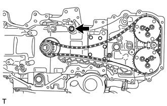
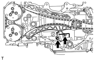
Using a 5 mm hexagon socket wrench, install the No. 1 chain vibration damper with the bolt.
- Torque:
- 6.4 N*m { 65 kgf*cm, 57 in.*lbf }
Tech Tips
Apply engine oil to the bolt before install it.
-
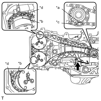
Install a new O-ring to the cylinder block (for bank 2).
-
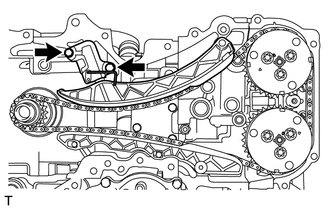
Install the chain tensioner slipper.
-
Install the No. 2 chain tensioner assembly with the 2 bolts.
- Torque:
- 6.4 N*m { 65 kgf*cm, 57 in.*lbf }
-
Text in Illustration *a Alignment Mark (Oval) *b Alignment Mark (Engraved Line) *c Mark plate (Grayish Blue) *d Mark plate (Pink) Check that the chain is correctly installed.
-
The mark plate (grayish blue) on the chain sub-assembly is aligned with the alignment mark (oval) on the crankshaft timing gear or sprocket.
-
The mark plate (pink) on the chain sub-assembly is aligned with the alignment mark (engraved line) on the camshaft timing intake gear assembly LH.
-
The mark plate (pink) on the chain sub-assembly is aligned with the alignment mark (engraved line) on the camshaft timing exhaust gear assembly LH.
-
-
Pull out the wire or the like from the No. 2 chain tensioner assembly.
-
Temporarily install the crankshaft pulley spacer and crankshaft pulley.
-
Using SST, turn the crankshaft clockwise to make sure that there are no abnormal conditions.
- SST
- 09960-10010 ( 09962-01000, 09963-01000 )
Note
Be sure to perform this confirmation.
-
-
INSTALL CHAIN SUB-ASSEMBLY (for Bank 1)
Note
Do not allow any foreign matter to adhere or to enter into the component parts during installation.
Tech Tips
Apply engine oil to all component parts of the chain sub-assembly.
-
Text in Illustration *1 Link Plate *2 Plunger Move the link plate in the direction of the arrow in the illustration to press in the plunger.
-
Text in Illustration *1 First notch of the plunger rack *2 Stopper Tooth Insert a 2.5 mm (0.098 in.) diameter hexagon wrench into the No. 1 chain tensioner assembly through the stopper pin hole, and hold the plunger.
Tech Tips
If the stopper pin hole on the link plate and the stopper pin hole on the chain tensioner assembly are not aligned, check that the first notch of the plunger rack is engaged with the stopper tooth. If not engaged, retract the plunger a little so that the first notch of the plunger rack is engaged with the stopper tooth.
-
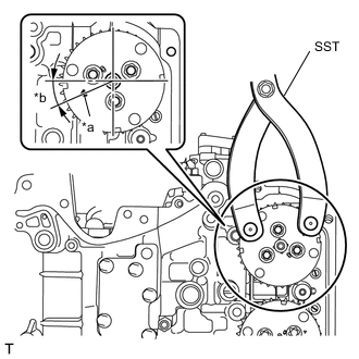
Text in Illustration *a Alignment Mark *b Crankshaft Pulley Pin Hole *c Crankshaft Timing Gear Key Using SST, turn the crankshaft pulley until the alignment marks on the camshaft timing intake gear assembly LH and the camshaft timing exhaust gear assembly LH, and the crankshaft pulley pin hole are aligned at the positions shown in the illustration.
- SST
- 09960-10010 ( 09962-01000, 09963-01000 )
Tech Tips
At this time, the alignment mark on the crankshaft timing gear or sprocket and the crankshaft timing gear key are at the positions shown in the illustration.
-
Remove the crankshaft pulley and crankshaft pulley spacer.
-
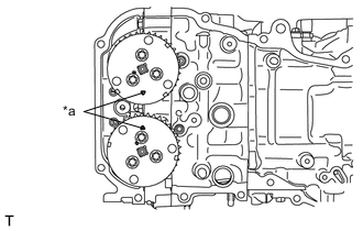
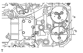
Text in Illustration *a Alignment Mark Align the alignment marks of the camshaft timing intake gear assembly RH and camshaft timing exhaust gear assembly RH as shown in the illustration.
Note
To avoid damaging the valves, do not turn the camshaft timing intake gear assembly RH and camshaft timing exhaust gear assembly RH more than the zero-lift range (The range where the camshafts can be turned lightly by hand).
-
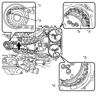
Text in Illustration *a Alignment Mark (Oval) *b Alignment Mark (Engraved Line) *c Mark plate (Grayish Blue) *d Mark plate (Pink) Install the chain sub-assembly in the following order.
-
Align the mark plate (grayish blue) on the chain sub-assembly with the alignment mark (oval) on the crankshaft timing gear or sprocket.
-
Align the mark plate (pink) on the chain sub-assembly with the alignment mark (engraved line) on the camshaft timing intake gear assembly RH.
-
Align the mark plate (pink) on the chain sub-assembly with the alignment mark (engraved line) on the camshaft timing exhaust gear assembly RH.
-
-
Using a 5 mm hexagon socket wrench, install the No. 1 chain vibration damper with the bolt.
- Torque:
- 6.4 N*m { 65 kgf*cm, 57 in.*lbf }
Tech Tips
Apply engine oil to the bolt before install it.
-
Install the chain tensioner slipper.
-
Install the No. 1 chain tensioner assembly with the 2 bolts.
- Torque:
- 6.4 N*m { 65 kgf*cm, 57 in.*lbf }
-
Text in Illustration *a Alignment Mark (Oval) *b Alignment Mark (Engraved Line) *c Mark plate (Grayish Blue) *d Mark plate (Pink) Check that the chain is correctly installed.
-
The mark plate (grayish blue) on the chain sub-assembly is aligned with the alignment mark (oval) on the crankshaft timing gear or sprocket.
-
The mark plate (pink) on the chain sub-assembly is aligned with the alignment mark (engraved line) on the camshaft timing intake gear assembly RH.
-
The mark plate (pink) on the chain sub-assembly is aligned with the alignment mark (engraved line) on the camshaft timing exhaust gear assembly RH.
-
-
Pull out the hexagon wrench from the No. 1 chain tensioner assembly.
-
Temporarily install the crankshaft pulley spacer and crankshaft pulley.
-
Using SST, turn the crankshaft clockwise to make sure that there are no abnormal conditions.
- SST
- 09960-10010 ( 09962-01000, 09963-01000 )
Note
Be sure to perform this confirmation.
-
Remove the crankshaft pulley and crankshaft pulley spacer.
-
-
INSTALL TIMING CHAIN OR BELT COVER SUB-ASSEMBLY
-
Apply a light layer of engine oil to 4 new O-rings and attach them to the engine.
-
Clean and degrease the contact surface.
-
If there are gaps at positions shown in the illustration, fill up with seal packing by using a sealer gun.
Seal packing Three Bond 1217G, 1217H or equivalent 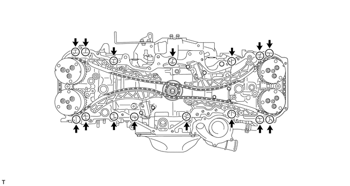
-
Using a sealer gun, apply seal packing in a continuous line as shown in the illustration.
Seal packing Three Bond 1217G, 1217H or equivalent 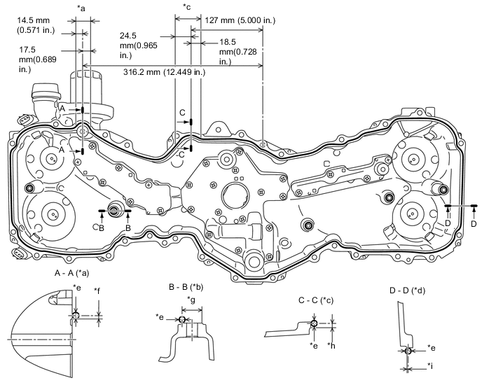
Text in Illustration *a Area A *b Boss (5 locations) *c Area B *d Other than ranges A and B *e φ3.5 to 4.5 mm (0.138 to 0.177 in.) *f 2.0 mm (0.079 in.) *g φ12 mm (0.472 in.) *h 2.5 mm (0.098 in.) *i 0.5 mm (0.0197 in.) - - Note
-
Clean and degrease the contact surface.
-
Install the chain cover within 5 minutes of applying seal packing.
-
-
Temporarily install the timing chain or belt cover sub-assembly with the 32 bolts.
-
Securely tighten the 32 bolts in the order as shown in the illustration.
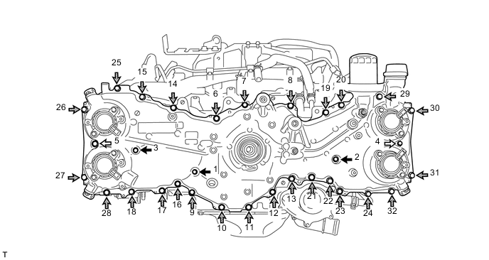
Text in Illustration Bolt A Bolt B 
Bolt C 
Bolt D - Torque:
- Bolt A and B
- 10 N*m { 102 kgf*cm, 7 ft.*lbf }
- Bolt C and D
- 25 N*m { 255 kgf*cm, 18 ft.*lbf }
Bolt Length Item Length Item Length Bolt A 20 mm (0.787 in.) Bolt B 50 mm (1.969 in.) Bolt C 25 mm (0.984 in.) Bolt D 60 mm (2.362 in.)
-
-
INSTALL TIMING CHAIN COVER OIL SEAL
-
Apply engine oil to a new oil seal lip.
Note
-
Keep the lip free from foreign matter.
-
Do not apply engine oil to the dust seal section.
-
-
Using SST and a hammer, tap in the new oil seal until its surface is flush with the timing chain or belt cover sub-assembly edge.
- SST
- 09950-60010 ( 09951-00460, 09951-00610, 09952-06010 )
- 09950-70010 ( 09951-07100 )
Note
-
Do not tap the oil seal at an angle.
-
Do not deform the oil seal.
Tech Tips
Alternatively, the tapping depth of the timing chain cover oil seal can be 0 to -1.0 mm (0 to -0.0394 in.) from the timing chain cover end surface.
-
-
INSTALL CRANKSHAFT PULLEY
-
Install the crankshaft pulley spacer.
-
Install a new O-ring to the crankshaft pulley spacer.
-
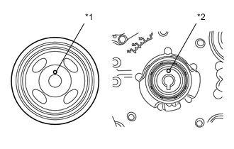
Text in Illustration *1 Knock Hole *2 Knock Pin Install the crankshaft pulley while aligning the knock hole of the pulley with the knock pin on the crankshaft pulley spacer.
-
Apply engine oil to threads and seat sections of the crankshaft pulley set bolt.
-
Text in Illustration *1 Claw Install SST to the crankshaft pulley.
- SST
- 09213-80010 ( 90179-10016, 09213-08010, 09213-08110 )
Tech Tips
Position the projections on SST in the direction as shown in the illustration to prevent SST from separating from the crankshaft pulley.
-
Text in Illustration *a Hold *b Turn Using SST, hold the crankshaft pulley and tighten the crankshaft pulley set bolt.
- SST
- 09213-80010 ( 90179-10016, 09213-08010, 09213-08110 )
- Torque:
- 20 N*m { 204 kgf*cm, 15 ft.*lbf }
-
Text in Illustration *a Reference Line A *b Reference Line B Using a marker, draw the reference line (A) on the crankshaft pulley set bolt and also the reference line (B) on the crankshaft pulley according to the line engraved around the crankshaft pulley set bolt head as shown in the illustration.
Tech Tips
There are carved lines on the crankshaft pulley set bolt head every 90°.
-
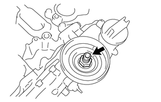
Text in Illustration *a Hold *b Turn *c Reference Line A *d Reference Line B Using SST, hold the crankshaft pulley, and tighten the crankshaft pulley set bolt by 90° until the reference lines A and B are aligned.
- SST
- 09213-80010 ( 90179-10016, 09213-08010, 09213-08110 )
-
-
INSTALL THERMOSTAT
-
Attach a new gasket to the thermostat.
-
-
INSTALL WATER OUTLET
-
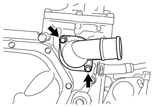
Install the thermostat and water outlet with the 2 bolts.
- Torque:
- 6.4 N*m { 65 kgf*cm, 57 in.*lbf }
-
-
INSTALL ENGINE WATER PUMP ASSEMBLY
-
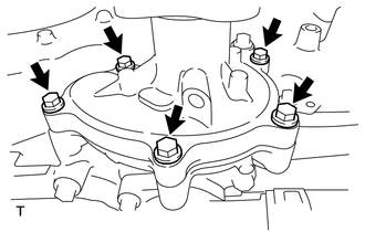
Install a new gasket and the water pump assembly with the 5 bolts.
- Torque:
- 6.4 N*m { 65 kgf*cm, 57 in.*lbf }
-
-
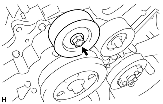
INSTALL WATER PUMP PULLEY
-
Temporarily install the water pump pulley with the 3 bolts.
-
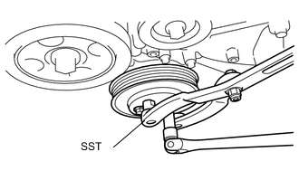
Using SST, hold the water pump pulley.
- SST
- 09960-10010 ( 09962-01000, 09963-00700 )
-
Securely tighten the 3 bolts.
- Torque:
- 14 N*m { 143 kgf*cm, 10 ft.*lbf }
-
-
INSTALL NO. 1 IDLER PULLEY SUB-ASSEMBLY
-
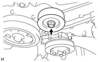
Install the idler pulley cover and No. 1 idler pulley sub-assembly with the bolt.
- Torque:
- 36 N*m { 367 kgf*cm, 27 ft.*lbf }
-
-
INSTALL NO. 1 IDLER PULLEY SUB-ASSEMBLY
-
Install the idler pulley cover and No. 1 idler pulley sub-assembly with the bolt.
- Torque:
- 36 N*m { 367 kgf*cm, 27 ft.*lbf }
-
-
INSTALL PCV VALVE SUB-ASSEMBLY
-
Text in Illustration *1 Adhesive 1141G Apply adhesive to 2 or 3 threads of the PCV valve sub-assembly.
Adhesive Three Bond 1141G or equivalent -
Using a 19 mm deep socket wrench, install the PCV valve sub-assembly.
- Torque:
- 23 N*m { 235 kgf*cm, 17 ft.*lbf }
-
-
INSTALL WATER INLET PIPE
-
Attach 2 new O-rings to the cylinder block.
-
Install the water inlet pipe with the 4 bolts.
- Torque:
- 6.4 N*m { 65 kgf*cm, 57 in.*lbf }
-
Connect the No. 3 water by-pass hose with the clamp.
-
-
INSTALL REAR CYLINDER HEAD PLATE (for Manual Transmission)
-
Text in Illustration *a φ2,0 to 4.0 mm (0.079 to 0.158 in.) *b Within 1.0 mm (0.0394 in.) *c Chamfer edge Using a sealer gun, apply seal packing in a continuous line as shown in the illustration.
Seal packing Three Bond 1217G, 1217H or equivalent Note
-
Clean and degrease the contact surface.
-
Install the rear cylinder head plate within 5 minutes of applying seal packing.
-
-
Install the rear cylinder head plate with the 3 bolts.
- Torque:
- 16 N*m { 163 kgf*cm, 12 ft.*lbf }
-
-
INSTALL VACUUM PUMP ASSEMBLY (for Automatic Transmission)
-
INSTALL PCV HOSE CONNECTOR
-
Connect the No. 2 water by-pass hose to the PCV hose connector and water inlet pipe with the clips.
-
Install the PCV hose connector with the 3 bolts.
- Torque:
- 6.4 N*m { 65 kgf*cm, 57 in.*lbf }
-
-
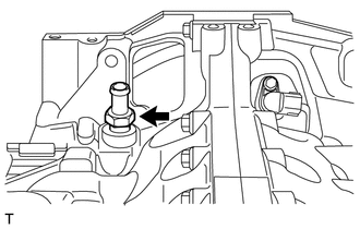
INSTALL ENGINE OIL PRESSURE SWITCH ASSEMBLY
-
Clean and degrease the threads of the engine oil pressure switch assembly.
-
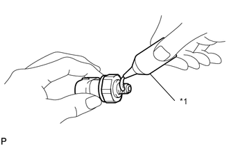
Text in Illustration *1 Adhesive 1324 Apply adhesive 1324 to the threads of the engine oil pressure switch assembly.
Adhesive Toyota Genuine Adhesive 1324, Three Bond 1324 or equivalent Note
Keep the oil hole free from adhesive.
-
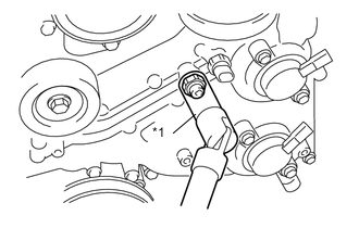
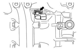
Text in Illustration *1 24 mm Deep Socket Wrench Using a 24 mm deep socket wrench, install the engine oil pressure switch assembly.
- Torque:
- 18 N*m { 184 kgf*cm, 13 ft.*lbf }
Note
Do not start the engine for at least 1 hour after installation.
-
-
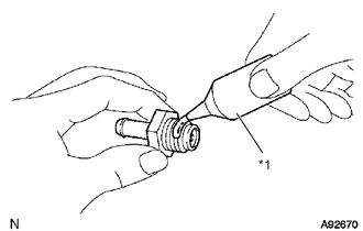
INSTALL ENGINE OIL TEMPERATURE SENSOR
-
Attach a new gasket to the engine oil temperature sensor.
-
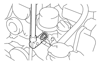
Text in Illustration *1 19 mm Deep Socket Wrench Using a 19 mm deep socket wrench, install the engine oil temperature sensor.
- Torque:
- 18 N*m { 184 kgf*cm, 13 ft.*lbf }
-
-
INSTALL CAMSHAFT TIMING OIL CONTROL VALVE
-
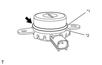
Text in Illustration *1 O-ring *2 Back-up ring Install the back-up ring to the camshaft timing oil control valve (for exhaust side of bank 2).
-
Install a new O-ring to the camshaft timing oil control valve (for exhaust side of bank 2).
-
Apply a light coat of engine oil to the O-ring.
-
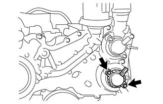
Install the camshaft timing oil control valve (for exhaust side of bank 2) with the 2 bolts.
- Torque:
- 6.4 N*m { 65 kgf*cm, 57 in.*lbf }
-
Install the back-up ring to the camshaft timing oil control valve (for intake side of bank 2).
-
Install a new O-ring to the camshaft timing oil control valve (for intake side of bank 2).
-
Apply a light coat of engine oil to the O-ring.
-
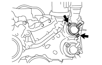
Install the camshaft timing oil control valve (for intake side of bank 2) with the 2 bolts.
- Torque:
- 6.4 N*m { 65 kgf*cm, 57 in.*lbf }
-
Install the back-up ring to the camshaft timing oil control valve (for exhaust side of bank 1).
-
Install a new O-ring to the camshaft timing oil control valve (for exhaust side of bank 1).
-
Apply a light coat of engine oil to the O-ring.
-
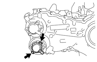
Install the camshaft timing oil control valve (for exhaust side of bank 1) with the 2 bolts.
- Torque:
- 6.4 N*m { 65 kgf*cm, 57 in.*lbf }
-
Install the back-up ring to the camshaft timing oil control valve (for intake side of bank 1).
-
Install a new O-ring to the camshaft timing oil control valve (for intake side of bank 1).
-
Apply a light coat of engine oil to the O-ring.
-
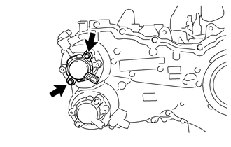
Install the camshaft timing oil control valve (for intake side of bank 1) with the 2 bolts.
- Torque:
- 6.4 N*m { 65 kgf*cm, 57 in.*lbf }
-
-
INSTALL VVT SENSOR
-
Install a new O-ring to the VVT sensor (for exhaust side of bank 2).
-
Apply a light coat of engine oil to the O-ring.
-
Install the VVT sensor (for exhaust side of bank 2) with the bolt.
- Torque:
- 6.4 N*m { 65 kgf*cm, 57 in.*lbf }
-
Install a new O-ring to the VVT sensor (for intake side of bank 2).
-
Apply a light coat of engine oil to the O-ring.
-
Install the VVT sensor (for intake side of bank 2) with the bolt.
- Torque:
- 6.4 N*m { 65 kgf*cm, 57 in.*lbf }
-
Install a new O-ring to the VVT sensor (for exhaust side of bank 1).
-
Apply a light coat of engine oil to the O-ring.
-
Install the VVT sensor (for exhaust side of bank 1) with the bolt.
- Torque:
- 6.4 N*m { 65 kgf*cm, 57 in.*lbf }
-
Install a new O-ring to the VVT sensor (for intake side of bank 1).
-
Apply a light coat of engine oil to the O-ring.
-
Install the VVT sensor (for intake side of bank 1) with the bolt.
- Torque:
- 6.4 N*m { 65 kgf*cm, 57 in.*lbf }
-
-
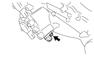
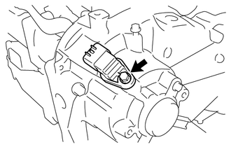
INSTALL CRANK POSITION SENSOR
-
Install the crank position sensor with the bolt.
- Torque:
- 6.4 N*m { 65 kgf*cm, 57 in.*lbf }
-
-
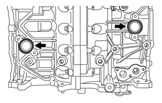
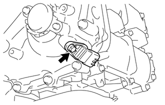
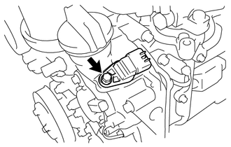
INSTALL KNOCK CONTROL SENSOR
-
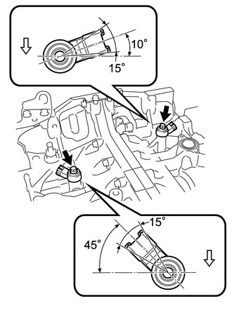
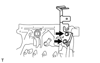
Install the 2 knock control sensors onto the cylinder block with the 2 bolts as shown in the illustration.
- Torque:
- 24 N*m { 245 kgf*cm, 18 ft.*lbf }
Text in Illustration Engine front
-
-
INSTALL E.F.I. WATER TEMPERATURE SENSOR
-
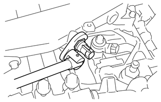
Using a 19 mm union nut wrench, install a new gasket and the E.F.I. water temperature sensor.
- Torque:
- 18 N*m { 184 kgf*cm, 13 ft.*lbf }
Note
Use the formula to calculate special torque values for situations where a union nut wrench is combined with a torque wrench Click here.
-
-
INSTALL OIL FILTER UNION
-
Install the oil filter union.
- Torque:
- 45 N*m { 459 kgf*cm, 33 ft.*lbf }
-
-
INSTALL OIL FILTER SUB-ASSEMBLY
-
Apply engine oil to the installation surface of the oil filter sub-assembly.
-
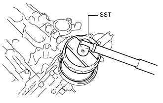
Using SST, install the oil filter sub-assembly.
- SST
- 09228-22020
- Torque:
- 14 N*m { 143 kgf*cm, 10 ft.*lbf }
-
-
INSTALL OIL FILLER CAP
-
Install the oil filler cap.
-