ENGINE UNIT INSPECTION

PROCEDURE
-
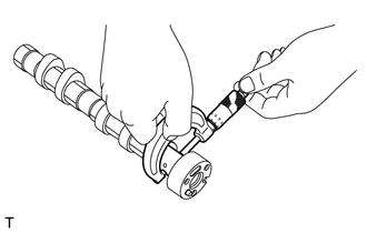
INSPECT NO. 1 VALVE ROCKER ARM SUB-ASSEMBLY
-
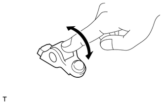
Check that the roller moves smoothly by rotating it by hand.
Replace the No. 1 valve rocker arm sub-assembly if the roller does not rotate smoothly.
-
-
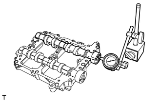
INSPECT CHAIN SUB-ASSEMBLY
-
Check the chain sub-assembly for deformation, cracks or other damages.
If the chain sub-assembly has any defects, replace it.
-
-
INSPECT CAMSHAFT TIMING GEAR
-
Check the camshaft timing gear teeth for abnormal wear and scratches.
If the camshaft timing gear has any defects, replace it.
-
-
INSPECT CRANKSHAFT TIMING GEAR OR SPROCKET
-
Check the crankshaft timing gear or sprocket teeth for abnormal wear and scratches.
If necessary, replace it.
-
Check that there is no play between the crankshaft timing gear or sprocket and the key.
If necessary, replace the crankshaft timing gear or sprocket or the key.
-
-
INSPECT CHAIN TENSIONER SLIPPER
-
Check the chain tensioner slipper for deformation, cracks or other damages.
-
-
INSPECT NO. 1 CHAIN VIBRATION DAMPER
-
Check the No. 1 chain vibration damper for deformation, cracks or other damages.
-
-
INSPECT CHAIN TENSIONER ASSEMBLY
-
Check the chain tensioner assembly for deformation, cracks or other damages.
-
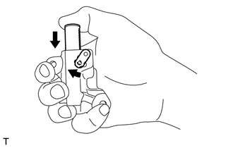
Check that the plunger moves smoothly when it is unlocked.
If the plunger does not move smoothly, replace the chain tensioner assembly.
-
Check that the plunger does not move when it is locked.
-
-
INSPECT CAMSHAFT HOUSING SUB-ASSEMBLY
-
Visually check the oil control valve filters, and if clogging is found, replace them with new ones.
-
Check the camshaft housing sub-assembly journals for damage and wear. Replace the camshaft housing sub-assembly if necessary.
-
-
INSPECT CAMSHAFT
-
Check the camshaft journals for damage and wear.
Replace the camshaft if necessary.
-
Check the cam face condition.
Replace the camshaft if uneven wear is found.
Tech Tips
Remove the minor faults by smoothing the surface with 400-grit sandpaper.
-
Inspect for runout.
-
Place the camshaft on V-blocks.
-
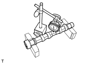
Using a dial indicator, measure the circle runout at the center journal.
Maximum circle runout 0.020 mm (0.00079 in.) If the circle runout is more than the maximum, replace the camshaft.
Tech Tips
Measurement should be performed at a temperature of 20°C (68°F).
-
-
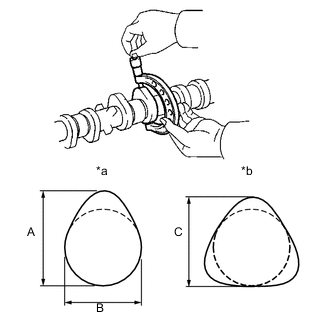
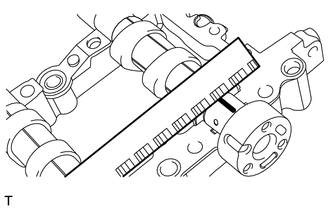
Text in Illustration *a For Valve *b For Fuel Pump Inspect for cam height.
-
Using a micrometer, measure the cam lobe height.
Standard height (Intake) Position Standard A 40.39 to 40.49 mm (1.5902 to 1.5941 in.) B 34.0 mm (1.3386 in.) Standard height (Exhaust) Position Standard A 40.19 to 40.29 mm (1.5823 to 1.5862 in.) B 34.0 mm (1.3386 in.) Standard height (For fuel pump) Position Standard C 38.95 to 39.05mm {1.5335 to 1.5374in} If the result is not as specified, replace the camshaft.
Tech Tips
Measurement should be performed at a temperature of 20°C (68°F).
-
-
Inspect for camshaft journals.
-
Using a micrometer, measure the journal diameter.
Standard journal diameter 25.946 to 25.963 mm (1.02149 to 1.02216 in.) If the result is not as specified, check the oil clearance.
Tech Tips
Measurement should be performed at a temperature of 20°C (68°F).
-
-
-
INSPECT CAMSHAFT OIL CLEARANCE
-
Using a dial indicator, measure the thrust clearance while moving the camshaft back and forth.
Standard thrust clearance 0.0068 to 0.1160 mm (0.00027 to 0.00457 in.) If the clearance is not as specified or if uneven wear is found, replace each camshaft cap and camshaft housing as a set. If necessary replace the camshaft.
Tech Tips
-
Measurement should be performed at a temperature of 20°C (68°F).
-
Set the dial indicator at the end surface of the camshaft.
-
-
-
INSPECT CAMSHAFT OIL CLEARANCE
Tech Tips
Measurement should be performed at a temperature of 20°C (68°F).
-
Remove the seal packing from camshaft housing and front camshaft cap, intake rear camshaft cap and exhaust rear camshaft cap.
-
Clean each camshaft cap and camshaft housing journal.
-
Set the camshafts on the camshaft housing.
-
Place a plastigauge across the camshaft journals and set the camshaft caps.
-
Tighten the bolts in the order shown in the illustration to install the front camshaft cap, intake center camshaft cap, intake rear camshaft cap, exhaust center camshaft cap and exhaust rear camshaft cap.
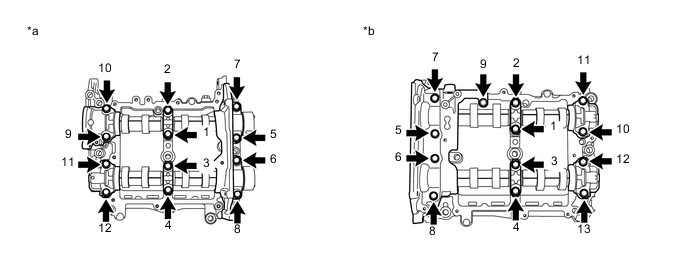
Text in Illustration *a for Bank 1 *b for Bank 2 - Torque:
- 18 N*m { 184 kgf*cm, 13 ft.*lbf }
-
Using several steps, uniformly loosen the bolts in the order shown in the illustration, and remove the front camshaft cap, intake center camshaft cap, intake rear camshaft cap, exhaust center camshaft cap and exhaust rear camshaft cap.
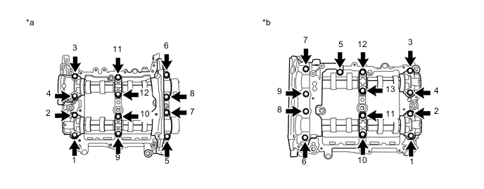
Text in Illustration *a for Bank 1 *b for Bank 2 -
Measure the widest point of the plastigauge on each journal.
Standard oil clearance 0.037 to 0.072 mm (0.00146 to 0.00283 in.) If the clearance is not as specified, replace each camshaft cap and camshaft housing as a set. If necessary, replace the camshaft.
-
Completely remove the plastigauge.
-