ENGINE UNIT DISASSEMBLY

PROCEDURE
-
REMOVE OIL FILLER CAP
-
Remove the oil filler cap.
-
-
REMOVE OIL FILTER SUB-ASSEMBLY
-
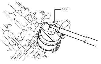
Using SST, remove the oil filter sub-assembly.
- SST
- 09228-22020
-
-
REMOVE OIL FILTER UNION
-
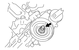
Remove the oil filter union.
-
-
REMOVE E.F.I. ENGINE COOLANT TEMPERATURE SENSOR
-
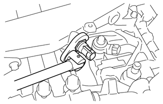
Using a 19 mm union nut wrench, remove the E.F.I. engine coolant temperature sensor.
-
-
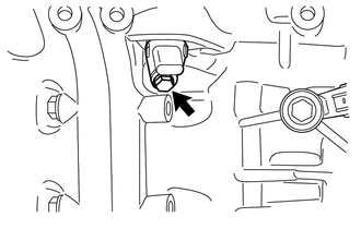
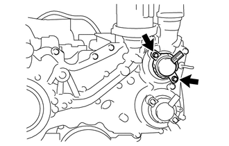
REMOVE KNOCK CONTROL SENSOR
-
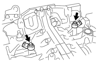
Remove the 2 bolts and 2 knock control sensors.
-
-
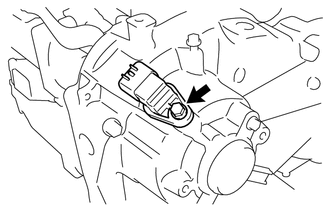
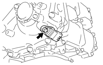
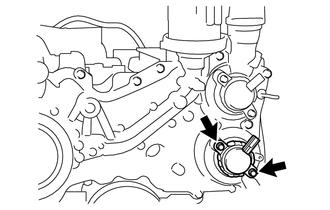
REMOVE CRANK POSITION SENSOR
-
Remove the bolt and crank position sensor.
-
-
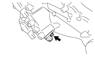
REMOVE VVT SENSOR
-
Remove the bolt and VVT sensor (for intake side of bank 1).
-
Remove the O-ring from the VVT sensor.
-
Remove the bolt and VVT sensor (for exhaust side of bank 1).
-
Remove the O-ring from the VVT sensor.
-
Remove the bolt and VVT sensor (for intake side of bank 2).
-
Remove the O-ring from the VVT sensor.
-
Remove the bolt and VVT sensor (for exhaust side of bank 2).
-
Remove the O-ring from the VVT sensor.
-
-
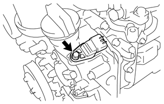
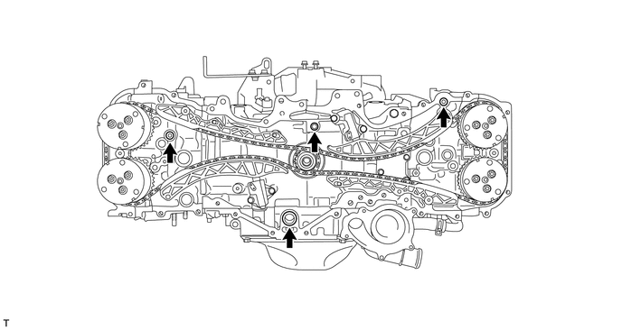
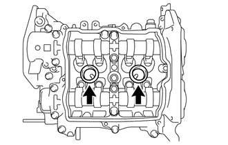
REMOVE CAMSHAFT TIMING OIL CONTROL VALVE
-
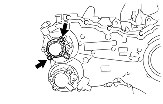
Remove the 2 bolts and camshaft timing oil control valve (for intake side of bank 1).
-
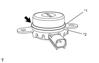
Remove the O-ring from the camshaft timing oil control valve.
-
Remove the back-up ring from the camshaft timing oil control valve.
Text in Illustration *1 O-ring *2 Back-up Ring -
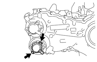
Remove the 2 bolts and camshaft timing oil control valve (for exhaust side of bank 1).
-
Remove the O-ring from the camshaft timing oil control valve.
-
Remove the back-up ring from the camshaft timing oil control valve.
-
Remove the 2 bolts and camshaft timing oil control valve (for intake side of bank 2).
-
Remove the O-ring from the camshaft timing oil control valve.
-
Remove the back-up ring from the camshaft timing oil control valve.
-
Remove the 2 bolts and camshaft timing oil control valve (for exhaust side of bank 2).
-
Remove the O-ring from the camshaft timing oil control valve.
-
Remove the back-up ring from the camshaft timing oil control valve.
-
-
REMOVE ENGINE OIL TEMPERATURE SENSOR
-
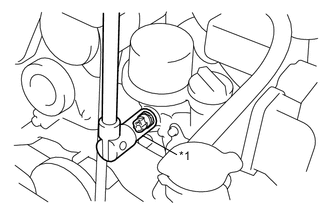
Text in Illustration *1 19 mm Deep Socket Wrench Using a 19 mm deep socket wrench, remove the engine oil temperature sensor.
Note
Use a cloth or the like to prevent engine oil from splashing.
-
-
REMOVE ENGINE OIL PRESSURE SWITCH ASSEMBLY
-
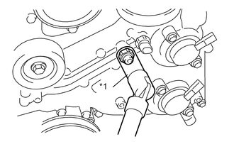
Text in Illustration *1 24 mm deep socket wrench Using a 24 mm deep socket wrench, remove the engine oil pressure switch assembly.
Note
Use a cloth or the like to prevent engine oil from splashing.
-
-
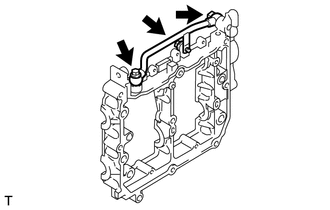
REMOVE PCV HOSE CONNECTOR
-
Remove the 3 bolts and PCV hose connector.
-
Loosen the 2 clips and remove the No. 2 water by-pass hose from the PCV hose connector.
-
-
REMOVE VACUUM PUMP ASSEMBLY (for Automatic Transmission)
-
REMOVE REAR CYLINDER HEAD PLATE (for Manual Transmission)
-
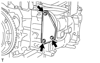
Remove the 3 bolts and rear cylinder head plate.
-
-
REMOVE WATER INLET PIPE
-
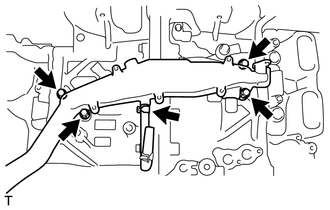
Disconnect the No. 3 water by-pass hose.
-
Remove the 4 bolts and water inlet pipe.
-
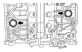
Remove the 2 O-rings from the cylinder block.
-
-
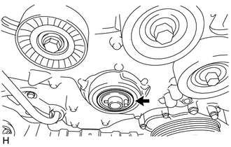
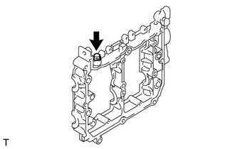
REMOVE PCV VALVE SUB-ASSEMBLY
-
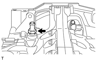
Using a 19 mm deep socket wrench, remove the PCV valve sub-assembly.
-
-
REMOVE NO. 1 IDLER PULLEY SUB-ASSEMBLY
-
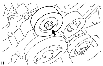
Remove the bolt, No. 1 idler pulley sub-assembly and idler pulley cover.
-
-
REMOVE NO. 1 IDLER PULLEY SUB-ASSEMBLY
-
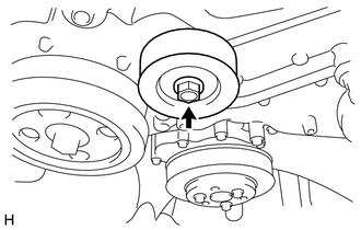
Remove the bolt, No. 1 idler pulley sub-assembly and idler pulley cover.
-
-
REMOVE WATER PUMP PULLEY
-
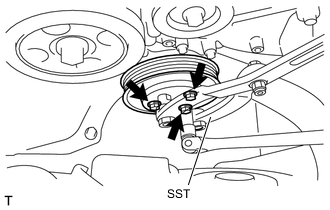
Using SST, hold the water pump pulley.
- SST
- 09960-10010 ( 09962-01000, 09963-00700 )
-
Remove the 3 bolts and water pump pulley.
-
-
REMOVE ENGINE WATER PUMP ASSEMBLY
-
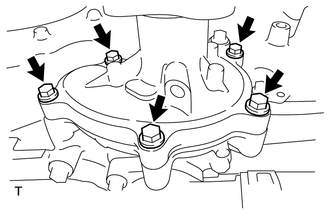
Remove the 5 bolts, engine water pump assembly and gasket.
-
-
REMOVE WATER OUTLET
-
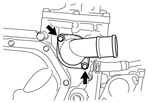
Remove the 2 bolts and water outlet.
-
-
REMOVE THERMOSTAT
-
Remove the thermostat.
-
Remove the gasket from the thermostat.
-
-
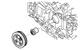
REMOVE CRANKSHAFT PULLEY
-
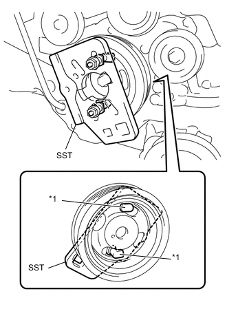
Text in Illustration *1 Claw Install SST to the crankshaft pulley.
- SST
- 09213-80010 ( 90179-10016, 09213-08010, 09213-08110 )
Tech Tips
Position the projections on SST in the direction as shown in the illustration to prevent SST from separating from the crankshaft pulley.
-
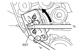
Text in Illustration *a Hold *b Turn Using SST, hold the crankshaft pulley and loosen the crankshaft pulley set bolt.
- SST
- 09213-80010 ( 90179-10016, 09213-08010, 09213-08110 )
-
Remove the crankshaft pulley.
-
Remove the O-ring and crankshaft pulley spacer.
-
-
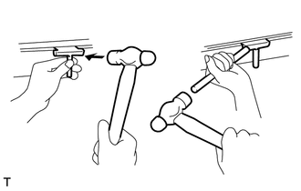
REMOVE TIMING CHAIN OR BELT COVER OIL SEAL
-
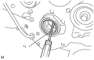
Text in Illustration *1 Protective Tape Using a screwdriver with its tip wrapped in protective tape, pry out the timing chain or belt cover oil seal.
Note
After the removal, check the crankshaft for damage. If it is damaged, smooth the surface with 400-grit sandpaper.
Tech Tips
Tape the screwdriver tip before use.
-
-
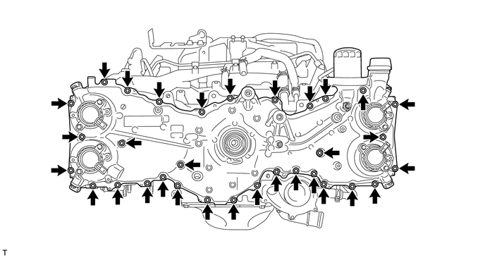
REMOVE TIMING CHAIN OR BELT COVER SUB-ASSEMBLY
-
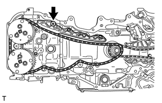
Remove the 32 bolts.
-
Using a screwdriver with its tip wrapped in protective tape, remove the timing chain or belt cover sub-assembly by prying between the timing chain or belt cover sub-assembly and cylinder head or cylinder block.
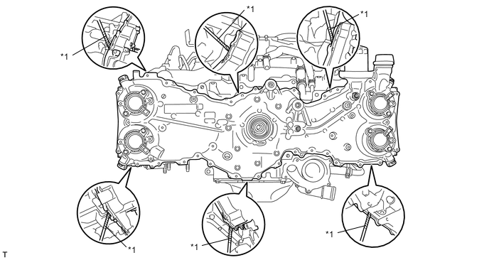
Text in Illustration *1 Protective Tape - - Note
Be careful not to damage the contact surfaces of the cylinder head, cylinder block or chain cover.
-
Remove the 4 O-rings.
-
-
MAKE PAINT MARKS
Tech Tips
If the alignment marks are difficult to identify during the work, mark the alignment marks with paint at the positions shown in the illustration, for easier recognition.
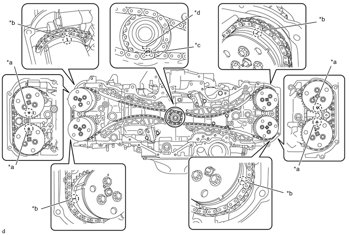
Text in Illustration *a Triangular Mark *b Engraved Line *c Oval Mark *d Crankshaft Timing Gear key -
REMOVE CHAIN SUB-ASSEMBLY (for Bank 1)
CAUTION:
Do not remove the chain sub-assembly from bank 2 at the same time as the chain sub-assembly is being removed from bank 1. Otherwise, the camshaft on bank 2 may turn suddenly, which is dangerous.
-
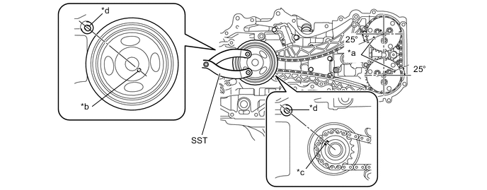
Temporarily install the crankshaft pulley spacer and crankshaft pulley.
-
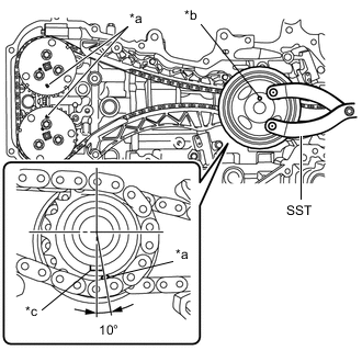
Text in Illustration *a Alignment Mark *b Crankshaft Pulley Pin Hole *c Crankshaft Timing Gear key Using SST, turn the crankshaft pulley clockwise until the alignment marks on the camshaft timing intake gear assembly RH and the camshaft timing exhaust gear assembly RH, and the crankshaft pulley pin hole are aligned at the positions shown in the illustration.
- SST
- 09960-10010 ( 09962-01000, 09963-01000 )
Tech Tips
At this time, the alignment mark on the crankshaft timing gear or sprocket and the crankshaft timing gear key are at the positions shown in the illustration.
-
Remove the crankshaft pulley and crankshaft pulley spacer.
-
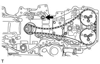
Push down the chain tensioner slipper and retain the plunger by inserting a 2.5 mm (0.098 in.) diameter hexagonal wrench into the No. 1 chain tensioner assembly through the stopper plate.
-
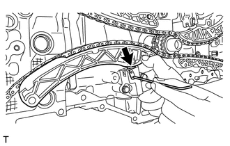
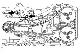
Remove the 2 bolts and No. 1 chain tensioner assembly.
-
Remove the chain tensioner slipper.
-
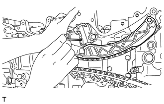
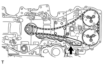
Using a 5 mm hexagonal wrench, remove the bolt and No. 1 chain vibration damper.
-
Remove the chain sub- assembly (for bank 1).
Note
-
With the chain sub- assembly (for bank 1) removed, the valve heads may contact each other if the camshafts are turned, causing the valve stems to bend.
-
To avoid this, do not turn the intake camshaft RH and the exhaust camshaft RH more than zero-lift range (The range where camshafts can be turned lightly by hand).
Tech Tips
Arrange the removed parts in the correct order.
-
-
-
REMOVE CHAIN SUB-ASSEMBLY (for Bank 2)
-
Temporarily install the crankshaft pulley spacer and crankshaft pulley.
-
Using SST, turn the crankshaft pulley clockwise until the alignment marks on the camshaft timing intake gear assembly LH and the camshaft timing exhaust gear assembly LH, and the crankshaft pulley pin hole are aligned at the positions shown in the illustration.
- SST
- 09960-10010 ( 09962-01000, 09963-01000 )
Text in Illustration *a Alignment Mark *b Crankshaft Pulley Pin Hole *c Crankshaft Timing Gear key *d Cylinder Block Guide Pin Tech Tips
At this time, the crankshaft timing gear key is at the position shown in the illustration.
-
Remove the crankshaft pulley and crankshaft pulley spacer.
-
Push the chain tensioner slipper and retain the plunger by inserting an approximately 1 mm (0.039 in.) diameter wire into the No. 2 chain tensioner assembly through the stopper plate .
-
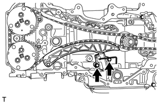
Remove the 2 bolts and No. 2 chain tensioner assembly.
-
Remove the chain tensioner slipper.
-
Remove the O-ring from the cylinder block.
-
Using a 5 mm socket hexagon wrench, remove the bolt and No. 1 chain vibration damper.
-
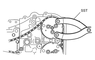
While releasing the tension of chain sub-assembly using SST, remove the chain sub-assembly.
- SST
- 09960-10010 ( 09962-01000, 09963-00700 )
CAUTION:
Make sure to use SST. Never carry out the work using only your hands.
Note
-
With the chain sub-assembly (for bank 2) removed, the valve heads may contact each other if the camshafts are turned, causing the valve stems to bend. To avoid this, do not turn the exhaust camshaft LH more than zero-lift rang (The range where the camshaft can be turned lightly by hand).
-
At this time, No. 1 and No. 4 pistons are located near TDC. If the intake camshaft is turned, the valves may come into contact with the piston, causing the valve stems to bend. To avoid this, do not turn the intake camshaft LH.
Tech Tips
Arrange the removed parts in the correct order.
-
-
ROTATE CRANK SHAFT AND CAMSHAFT
-
REMOVE CRANKSHAFT TIMING GEAR OR SPROCKET
-
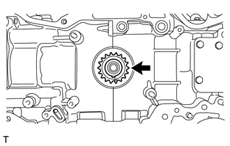
Remove the crankshaft timing gear or sprocket.
-
-
REMOVE CAMSHAFT TIMING INTAKE GEAR ASSEMBLY RH
-
REMOVE CAMSHAFT TIMING EXHAUST GEAR ASSEMBLY RH
-
REMOVE CAMSHAFT TIMING INTAKE GEAR ASSEMBLY LH
-
REMOVE CAMSHAFT TIMING EXHAUST GEAR ASSEMBLY LH
-
REMOVE SPARK PLUG
-
Using a 14 mm spark plug wrench, remove the 4 spark plugs.
-
-
REMOVE INJECTOR DRIVER BRACKET
-
Remove the 2 bolts and injector driver bracket.
-
-
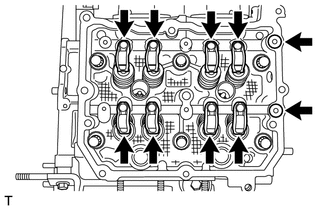
REMOVE CYLINDER HEAD COVER SUB-ASSEMBLY RH
-
Operate the engine stand so that the bank 1 side faces upward.
-
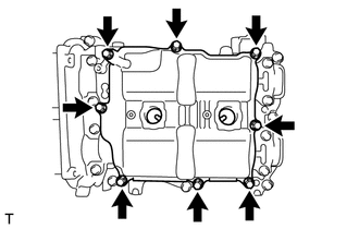
Remove the 8 bolts.
-
Using a screwdriver with its tip wrapped in protective tape, remove the cylinder head cover sub-assembly RH.
Note
Do not damage the camshaft housing sub-assembly RH, cam caps and cylinder head cover sub-assembly RH.
-
Remove the cylinder head cover gasket.
-
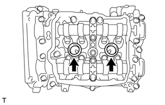
Remove the 2 spark plug tube gaskets.
Note
When removing the seal packing left on the camshaft housing sub-assembly RH using a scraper, use special care not to damage the camshafts.
-
-
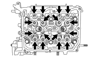
REMOVE CAMSHAFT HOUSING SUB-ASSEMBLY RH
Note
Do not remove the intake and exhaust camshafts first as it may cause a deformation of the cylinder head sub-assembly.
-
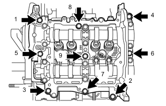
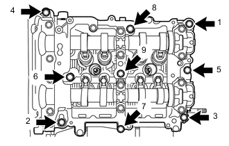
Loosen the 9 bolts in the order shown in the illustration and remove them.
-
Using a screwdriver with its tip wrapped in protective tape, remove the camshaft housing sub-assembly RH.
Note
Do not damage the cylinder head sub-assembly RH and camshaft housing sub-assembly RH.
-
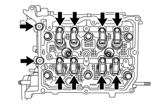
Remove the 2 O-rings and 8 No. 1 valve rocker arm sub-assemblies from the cylinder head sub-assembly.
Tech Tips
Arrange the removed parts in the correct order.
-
Remove the 8 valve adjusting shims and 8 roller rocker arm pivots from the cylinder head sub-assembly.
Tech Tips
-
Arrange the removed parts in the correct order.
-
When installing, be sure to install the removed parts in their original locations.
-
-
-
REMOVE CYLINDER HEAD SUB-ASSEMBLY RH
-
REMOVE CYLINDER HEAD GASKET
-
REMOVE CYLINDER HEAD COVER SUB-ASSEMBLY LH
-
Operate the engine stand so that the bank 2 side faces upward.
-
Remove the 8 bolts.
-
Using a screwdriver with its tip wrapped in protective tape, remove the cylinder head cover sub-assembly LH.
Note
Do not damage the camshaft housing sub-assembly LH, cam caps and cylinder head cover sub-assembly LH.
-
Remove the cylinder head cover gasket.
-
Remove the 2 spark plug tube gaskets.
Note
When removing the seal packing left on the camshaft housing sub-assembly LH using a scraper, use special care not to damage the camshafts.
-
-
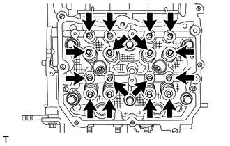
REMOVE CAMSHAFT HOUSING SUB-ASSEMBLY LH
Note
Do not remove the intake and exhaust camshafts first as it may cause a deformation of the camshaft housing sub-assembly LH.
-
Loosen the 9 bolts in the order shown in the illustration and remove them.
-
Using a screwdriver with its tip wrapped in protective tape, remove the camshaft housing sub-assembly LH.
Note
Do not damage the cylinder head sub-assembly LH and camshaft housing sub-assembly LH.
-
Remove the 2 O-rings and 8 No. 1 valve rocker arm sub-assemblies from the cylinder head sub-assembly LH.
Tech Tips
Arrange the removed parts in the correct order.
-
Remove the 8 valve adjusting shims and 8 roller rocker arm pivots from the cylinder head sub-assembly LH.
Tech Tips
-
Arrange the removed parts in the correct order.
-
When installing, be sure to install the removed parts in their original locations.
-
-
-
REMOVE CYLINDER HEAD SUB-ASSEMBLY LH
-
REMOVE NO. 2 CYLINDER HEAD GASKET
-
REMOVE NO. 2 ENGINE HANGER
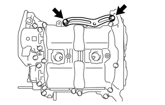
-
Remove the 2 bolts and No. 2 engine hanger from the cylinder block (for bank 1).
-
-
REMOVE NO. 2 OIL PAN SUB-ASSEMBLY
-
Remove the drain plug and gasket.
-
Remove the 11 bolts.
-
Using an oil pan seal cutter, remove the No. 2 oil pan sub-assembly.
Note
Do not damage the contact surface and flange part of the No. 2 oil pan sub-assembly.
-
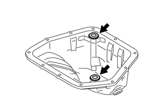
Remove the 2 seal rings from the No. 2 oil pan sub-assembly.
-
-
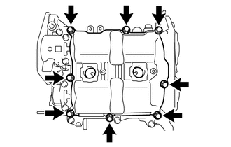
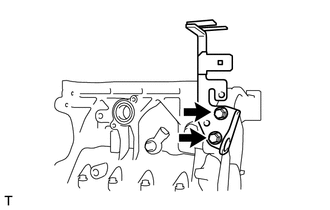
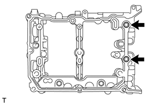
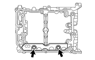
REMOVE OIL STRAINER SUB-ASSEMBLY
-
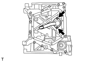
Remove the 2 bolts and oil strainer sub-assembly.
-
Remove the O-ring.
-
-
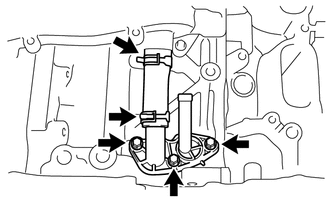
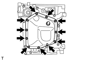
REMOVE OIL PAN SUB-ASSEMBLY
-
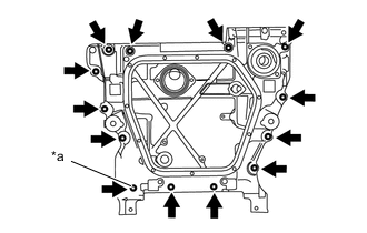
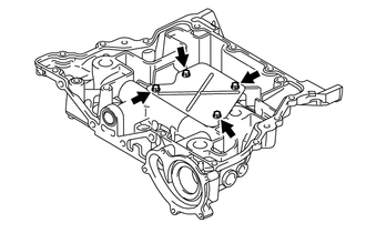
Text in Illustration *a Use a TORX Socket Wrench T45 Remove the 13 bolts.
-
Using a screwdriver with its tip wrapped in protective tape, remove the oil pan sub-assembly.
Note
Do not damage the cylinder block and oil pan sub-assembly.
-
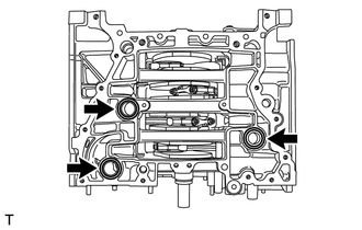
Remove the 3 O-rings from the cylinder block.
-
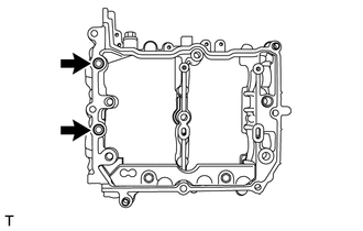
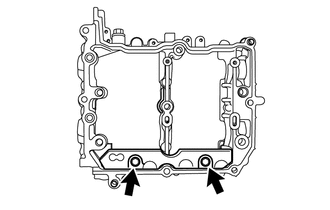
Remove the 4 bolts and baffle plate from the oil pan sub-assembly.
-
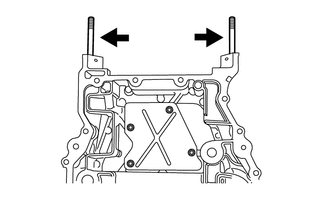
Remove the 2 stud bolts from the oil pan sub-assembly.
-
-
REMOVE CAMSHAFT BEARING CAP (for Bank 1)
-
REMOVE CAMSHAFT (for Bank 1)
-
REMOVE OIL CONTROL VALVE FILTER (for Bank 1)
-
Remove the 2 oil control valve filters from the camshaft housing sub-assembly RH.
-
-
REMOVE OIL SPACER RH
-
Remove the 2 bolts and oil spacer RH.
-
-
REMOVE CAMSHAFT OIL FEED PIPE SUB-ASSEMBLY (for Automatic Transmission)
-
Remove the 2 union bolts, the bolt, camshaft oil feed pipe sub-assembly and 2 gaskets from the camshaft housing sub-assembly RH.
-
-
REMOVE HOLE PLUG (for Manual Transmission)
-
Remove the hole plug and gasket from the camshaft housing sub-assembly RH.
-
-
REMOVE CAMSHAFT BEARING CAP (for Bank 2)
-
REMOVE CAMSHAFT (for Bank 2)
-
REMOVE OIL CONTROL VALVE FILTER (for Bank 2)
-
Remove the 2 oil control valve filters from the camshaft housing sub-assembly LH.
-
-
REMOVE OIL SPACER LH
-
Remove the 2 bolts and oil spacer LH.
-