ENGINE ASSEMBLY REMOVAL

PROCEDURE
-
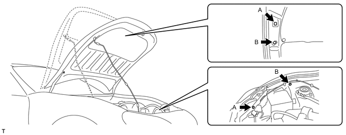
SET HOOD SUB-ASSEMBLY
-
Change the front hood stay position from A to B, and support the hood sub-assembly at position B.
-
-
RECOVER REFRIGERANT FROM REFRIGERATION SYSTEM (w/ Air Conditioning System)
-
for HFC-134a (R134a):
-
for HFO-1234yf (R1234yf):
-
-
DISCHARGE FUEL SYSTEM PRESSURE
-
DISCONNECT CABLE FROM NEGATIVE BATTERY TERMINAL
-
REMOVE FRONT SUSPENSION UPPER TO COWL BRACE SUB-ASSEMBLY LH
-
REMOVE FRONT SUSPENSION UPPER TO COWL BRACE SUB-ASSEMBLY RH
-
REMOVE AIR CLEANER CAP WITH AIR CLEANER HOSE
-
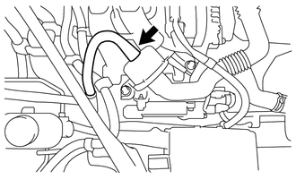
Disconnect the hose.
-
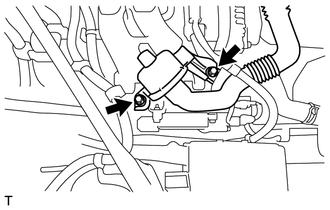
Remove the 2 bolts and disconnect the chamber.
-
Loosen the hose clamp and disconnect the No. 2 ventilation hose.
-
Disconnect the mass air flow meter connector.
-
Disengage the clamp and separate the wire harness from the air cleaner cap.
-
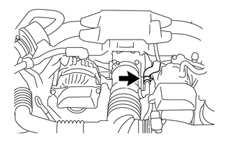
Loosen the hose clamp.
-
Remove the 3 bolts and air cleaner cap with air cleaner hose.
-
Remove the bolt and stay from the body.
-
-
DRAIN ENGINE OIL
-
DRAIN ENGINE COOLANT
-
REMOVE RADIATOR RESERVE TANK ASSEMBLY
-
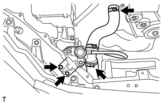
REMOVE WATER FILLER SUB-ASSEMBLY
-
Remove the 2 bolts and disconnect the water filler sub-assembly.
-
Remove the 2 clamps and water filler sub-assembly.
-
-
REMOVE INJECTOR DRIVER
-
DISCONNECT ENGINE WIRE (for RHD)
Tech Tips
Fix the disconnected harness components with tape to keep them out of the way.
-
for Automatic Transmission:
-
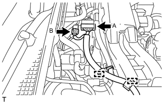
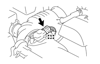
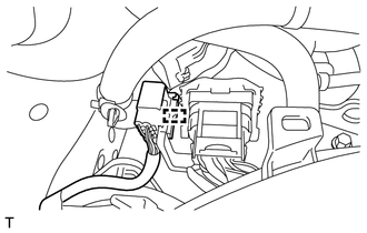
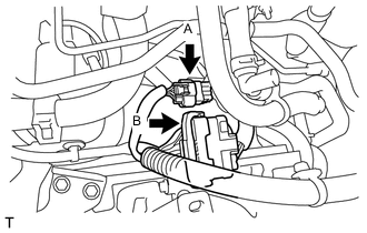
Release the lock of connector (A) and disconnect the connector.
-
Disconnect the connector (B).
-
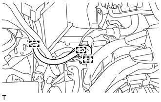
Disconnect the 2 wire harness clamps.
-
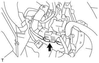
Slide the connector in the direction shown in the illustration, and disconnect the wire harness.
-
-
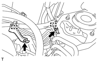
Remove the 2 bolts and the wire harness bracket from the No. 2 engine hanger.
-
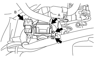
Release the lock of connector (A) and disconnect the connector.
-
Disconnect the connector (B).
-
Disconnect the wire harness clamp and wire harness from the No. 2 engine hanger.
-
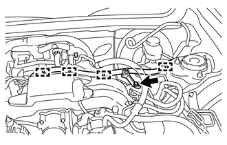
Disconnect the 2 wire harness clamps.
-
Remove the 2 bolts and 2 wire harness clamp brackets.
-
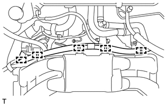
Disconnect the 5 wire harness clamps.
-
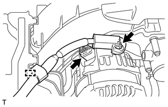
Disconnect the terminal cap.
-
Remove the nut and disconnect the wire harness from terminal B.
-
Disconnect the generator connector and disengage the clamp.
-
-
DISCONNECT ENGINE WIRE (for LHD)
Tech Tips
Fix the disconnected harness components with tape to keep them out of the way.
-
Remove the 2 bolts and the wire harness clamp bracket from the No. 2 engine hanger.
-
Release the lock of connector (A) and disconnect the connector.
-
Disconnect the connector (B).
-
Disconnect the connector.
-
Disconnect the wire harness clamp and wire harness from the No. 2 engine hanger.
-
Disconnect the 3 wire harness clamps.
-
for Automatic Transmission:
-
Release the lock of connector (A) and disconnect the connector.
-
Disconnect the connector (B).
-
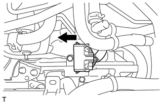
Slide the connector in the direction shown in the illustration, and disconnect the wire harness.
-
Disconnect the 4 wire harness clamps.
-
Remove the bolt and wire harness clamp bracket.
-
-
Disconnect the terminal cap.
-
Remove the nut and disconnect the wire harness from terminal B.
-
Disconnect the generator connector and disengage the clamp.
-
-
REMOVE NO. 1 ENGINE COVER SUB-ASSEMBLY
for Resin Intake Manifold:
-
DISCONNECT VACUUM TUBE CONNECTOR HOSE (for Automatic Transmission)
-
for LHD:
-
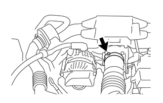
Loosen the hose clamp and disconnect the vacuum tube connector hose.
-
Remove the 2 bolts and disconnect the vacuum tube connector hose.
-
-
for RHD:
-
Loosen the hose clamp and disconnect the union to check valve hose.
-
-
-
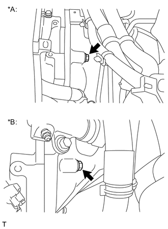
DISCONNECT VACUUM TUBE CONNECTOR HOSE (for Manual Transmission)
-
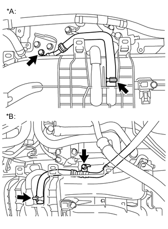
Text in Illustration *A for LHD *B for RHD Loosen the hose clamp and disconnect the union to check valve hose from the intake manifold.
-
-
REMOVE EXHAUST MANIFOLD
-
FIX FRONT EXHAUST PIPE SUB-ASSEMBLY (for Manual Transmission)
-
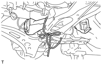
Tie the front exhaust pipe sub-assembly to the front cross member sub-assembly with rope.
-
-
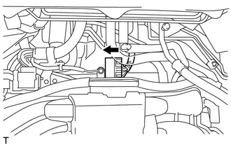
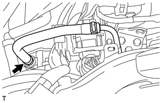
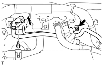
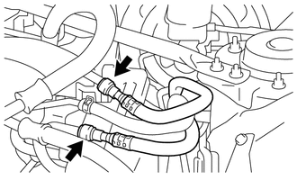
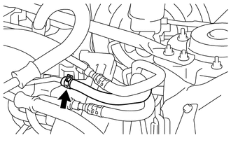
DISCONNECT HEATER WATER HOSE
-
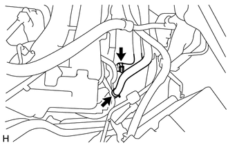
Loosen the 2 hose clamps and disconnect the 2 heater water hoses.
-
-
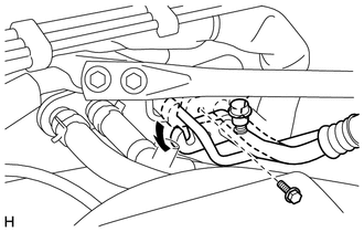
DISCONNECT NO. 1 TRANSMISSION OIL COOLER HOSE (for Automatic Transmission)
-
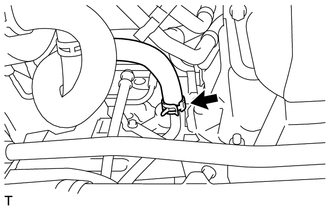
Loosen the clip and disconnect the No. 1 transmission oil cooler hose.
-
-
REMOVE SUCTION HOSE SUB-ASSEMBLY (w/ Air Conditioning System)
-
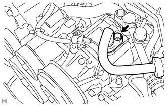
Remove the bolt and disconnect the suction hose sub-assembly from the compressor assembly with pulley.
-
Remove the O-ring from the discharge hose sub-assembly.
Note
Seal the openings of the disconnected parts using vinyl tape to prevent entry of moisture and foreign matter.
-
for LHD:
-
Remove the bolt and slide the hook connector.
-
Remove the nut and suction pipe sub-assembly.
-
Remove the O-ring from the suction pipe sub-assembly.
Note
Seal the openings of the disconnected parts using vinyl tape to prevent entry of moisture and foreign matter.
-
-
for RHD:
-
Remove the bolt and slide the hook connector.
-
Disconnect the suction pipe sub-assembly.
-
Remove the O-ring from the suction pipe sub-assembly.
Note
Seal the openings of the disconnected parts using vinyl tape to prevent entry of moisture and foreign matter.
-
-
-
DISCONNECT NO. 1 COOLER REFRIGERANT DISCHARGE HOSE (w/ Air Conditioning System)
-
REMOVE STARTER ASSEMBLY (for Automatic Transmission)
-
REMOVE STARTER ASSEMBLY (for Manual Transmission)
-
DISCONNECT NO. 3 TRANSMISSION OIL COOLER HOSE (for Automatic Transmission)
-
Loosen the clip and disconnect the No. 3 transmission oil cooler hose.
-
-
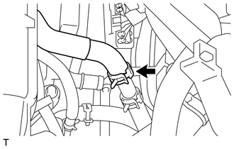
DISCONNECT RADIATOR OUTLET HOSE
-
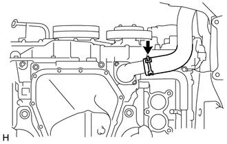
Loosen the clip and disconnect the radiator outlet hose.
-
-
DISCONNECT GROUNDED CABLE
-
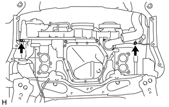
Remove the 2 bolts and disconnect the 2 grounded cables.
-
-
REMOVE REAR ENGINE UNDER COVER LH (w/ Floor Under Cover)
-
Remove the 3 bolts and 8 clips, then remove the rear engine under cover LH.
-
-
REMOVE FRONT STABILIZER BAR (for Automatic Transmission)
-
FIX FRONT EXHAUST PIPE ASSEMBLY (for Automatic Transmission)
-
Tie the front exhaust pipe assembly to the front cross member sub-assembly with rope.
-
-
SEPARATE AUTOMATIC TRANSMISSION ASSEMBLY (for Automatic Transmission)
-
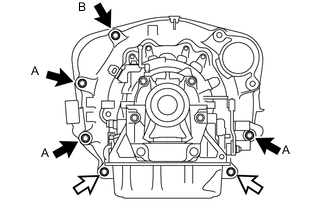
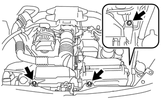
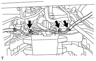
Remove the 3 bolts and 2 nuts.
Text in Illustration 
Bolt 
Nut Note
In order to prevent dropping, do not remove bolt B.
-
-
REMOVE MANUAL TRANSMISSION ASSEMBLY (for Manual Transmission)
-
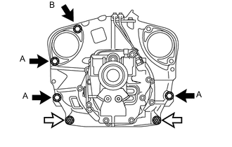
Remove the 3 bolts and 2 nuts.
Text in Illustration Bolt Nut Note
In order to prevent dropping, do not remove bolt B.
-
-
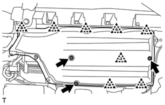
SEPARATE FRONT CROSS MEMBER SUB-ASSEMBLY
-
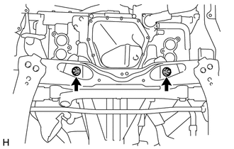
Remove the 2 nuts from the front cross member sub-assembly.
-
-
REMOVE FLYWHEEL HOUSING UNDER COVER
-
REMOVE DRIVE PLATE SETTING HEXAGON BOLT (for Automatic Transmission)
-
SEPARATE FUEL HOSE
-
for Clamp Type:
-
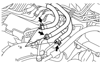
Text in Illustration *a matchmark Put matchmarks on the fuel hoses and fuel pipes.
-
Remove the clamp and disconnect the fuel tube, No. 2 fuel tube and fuel tube from the fuel pipe.
-
-
for Metal Type:
-
Using SST, disconnect the fuel tube and No. 2 fuel tube from the fuel pipe Click here.
- SST
- SU003-03936
-
Remove the clamp and disconnect the No. 2 fuel vapor feed hose from the fuel pipe.
-
-
-
INSTALL ENGINE HANGER
-

Text in Illustration *1 No. 1 Engine Hanger *2 No. 2 Engine Hanger Install the engine hanger with the bolt, as shown in the illustration.
- Torque:
- 43 N*m { 439 kgf*cm, 32 ft.*lbf }
Tech Tips
No. 1 Engine Hanger 12281-38030 Bolt 90119-14120 -
Use an engine sling device and a mini crane to hold the engine.
-
-
SUPPORT TRANSMISSION ASSEMBLY
-
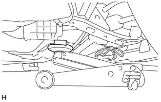
Support the transmission assembly clutch housing with a jack.
Note
Support the transmission assembly until the installation of the engine assembly is completed.
-
-
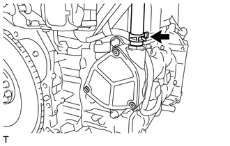
REMOVE ENGINE ASSEMBLY
-
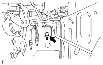
Text in Illustration *A for Automatic Transmission *B for Manual Transmission Remove the bolt from the transmission assembly.
-
Hoist the engine assembly up with an engine sling device and a mini crane.
-
-
REMOVE DRIVE PLATE AND RING GEAR SUB-ASSEMBLY (for Automatic Transmission)
-
REMOVE CLUTCH COVER ASSEMBLY (for Manual Transmission)
-
REMOVE CLUTCH DISC ASSEMBLY (for Manual Transmission)
-
REMOVE FLYWHEEL SUB-ASSEMBLY (for Manual Transmission)
-
REMOVE NO. 1 CRANKSHAFT POSITION SENSOR PLATE
-
INSTALL ENGINE STAND
-
Set the engine on an engine stand.
Note
With the exception of installing the engine assembly to an engine stand or removing the engine assembly from an engine stand, do not perform any work on the engine while it is suspended, as doing so is dangerous.
-
-
REMOVE FRONT ENGINE MOUNTING BRACKET
-
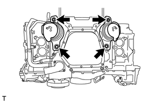
Remove the 4 bolts and 2 front engine mounting brackets.
-