FRONT CRANKSHAFT OIL SEAL INSTALLATION

PROCEDURE
-
INSTALL TIMING CHAIN OR BELT COVER OIL SEAL
-
Apply engine oil to the lip of a new timing chain or belt cover oil seal.
Note
-
Keep the lip free of foreign matter.
-
Do not apply engine oil to the dust seal section.
-
-
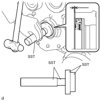
Using SST and a hammer, tap in the timing chain or belt cover oil seal until its surface is flush with the timing chain cover edge.
- SST
- 09950-60010 ( 09951-00460, 09951-00610, 09952-06010 )
- 09950-70010 ( 09951-07100 )
Note
-
Keep the lip free of foreign matter.
-
Do not tap the oil seal at an angle.
Tech Tips
Alternatively, the tapping depth of the timing chain or belt cover oil seal can be -1.0 to 0 mm (-0.039 to 0 in.) from the timing chain cover end surface.
-
-
INSTALL CRANKSHAFT PULLEY
-
Install the crankshaft pulley spacer.
-
Install a new O-ring to the crankshaft pulley spacer.
-
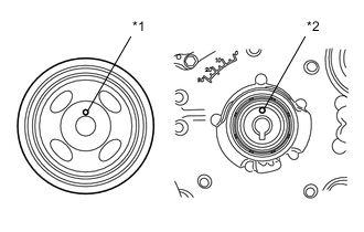
Text in Illustration *1 Knock Hole *2 Knock Pin Install the crankshaft pulley while aligning the knock hole of the pulley with the knock pin on the crankshaft pulley spacer.
-
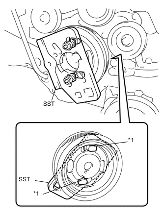
Text in Illustration *1 Claw Install SST to the crankshaft pulley.
- SST
- 09213-80010 ( 90179-10016, 09213-08010, 09213-08110 )
Tech Tips
Position the projections on SST in the direction as shown in the illustration to prevent SST from separating from the crankshaft pulley.
-
Apply engine oil to the crankshaft pulley set bolt.
-
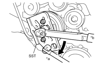
Text in Illustration *a Hold *b Turn Using SST, hold the crankshaft pulley and tighten the crankshaft pulley set bolt.
- SST
- 09213-80010 ( 90179-10016, 09213-08010, 09213-08110 )
- Torque:
- 20 N*m { 204 kgf*cm, 15 ft.*lbf }
-
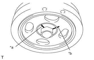
Text in Illustration *a Reference Line A *b Reference Line B Using a marker, draw the reference line (A) on the crankshaft pulley set bolt and also the reference line (B) on the crankshaft pulley according to the line engraved around the crankshaft pulley set bolt head as shown in the illustration.
Tech Tips
There are carved lines on the crankshaft pulley set bolt head every 90°.
-
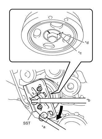
Text in Illustration *a Hold *b Turn *c Reference Line A *d Reference Line B Using SST, hold the crankshaft pulley, and tighten the crankshaft pulley set bolt by 90° until the reference lines A and B are aligned.
- SST
- 09213-80010 ( 90179-10016, 09213-08010, 09213-08110 )
-
-
INSTALL FAN AND GENERATOR V BELT