CAMSHAFT INSTALLATION

PROCEDURE
-
INSTALL CAMSHAFT LH (for Bank 2)
-
Apply engine oil to the journals of the camshaft housing sub-assembly LH.
-
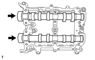
Set the intake camshaft LH and the exhaust camshaft LH to the camshaft housing sub-assembly LH.
-
-
INSTALL CAMSHAFT CAP (for Bank 2)
-
Using a sealer gun, apply seal packing to the contact surface of the front camshaft cap LH, intake rear camshaft cap LH and exhaust rear camshaft cap LH as shown in the illustration.
Seal packing Three Bond 1217G, 1217H or equivalent 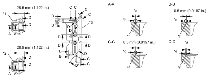
Text in Illustration *1 Intake Rear Camshaft Cap LH *2 Exhaust Rear Camshaft Cap LH *3 Front Camshaft Cap LH - - *a Within 1.0 mm (0.0394 in.) *b φ3.0 to 4.0 mm (0.1181 to 0.1575 in.) *c φ2.5 to 3.5 mm (0.0984 to 0.1378 in.) *d φ2.5 to 4.0 mm (0.0984 to 0.1575 in.) *e φ1.5 to 2.5 mm (0.0591 to 0.0984 in.) *f Chamfer edge Note
-
Clean and degrease the contact surface.
-
Do not apply excessively seal packing as it may cause excess seal packing to flow toward the cam journal, resulting in engine seizure.
-
Do not apply seal packing to the intake center camshaft cap LH and exhaust center camshaft cap LH.
-
Install the camshaft caps within 5 minutes of applying the seal packing.
-
-
Apply engine oil to the journals of the camshaft caps, and place them on the camshaft housing sub-assembly LH.
-
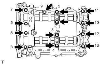
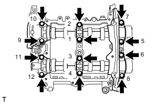
Tighten the 13 bolts in the order shown in the illustration to install the front camshaft cap LH, intake center camshaft cap LH, intake rear camshaft cap LH, exhaust center camshaft cap LH and exhaust rear camshaft cap LH.
- Torque:
- 18 N*m { 184 kgf*cm, 13 ft.*lbf }
-
-
INSTALL CAMSHAFT RH (for Bank 1)
-
Apply engine oil to the journals of the camshaft housing sub-assembly RH.
-
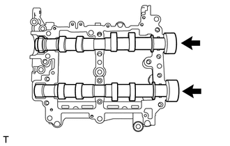
Set the intake camshaft RH and the exhaust camshaft RH to the camshaft housing sub-assembly RH.
-
-
INSTALL CAMSHAFT CAP (for Bank 1)
-
Using a sealer gun, apply seal packing to the contact surface of the front camshaft cap RH, intake rear camshaft cap RH and exhaust rear camshaft cap RH as shown in the illustration.
Seal packing Three Bond 1217G, 1217H or equivalent 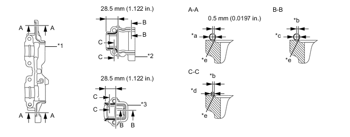
Text in Illustration *1 Front Camshaft Cap RH *2 Intake Rear Camshaft Cap RH *3 Exhaust Rear Camshaft Cap RH - - a φ2.5 to 4.0 mm (0.0984 to 0.1575 in.) b Within 1.0 mm (0.0394 in.) c φ3.0 to 4.0 mm (0.1181 to 0.1575 in.) d φ1.5 to 2.5 mm (0.0591 to 0.0984 in.) e Chamfer edge - - Note
-
Clean and degrease the contact surface.
-
Do not apply excessively seal packing as it may cause excess seal packing to flow toward the cam journal, resulting in engine seizure.
-
Do not apply seal packing to the intake center camshaft cap RH and exhaust center camshaft cap RH.
-
Install the camshaft caps within 5 minutes of applying the seal packing.
-
-
Apply engine oil to the journals of the camshaft caps, and place them on the camshaft housing sub-assembly RH.
-
Tighten the 12 bolts in the order shown in the illustration to install the front camshaft cap RH, intake center camshaft cap RH, intake rear camshaft cap RH, exhaust center camshaft cap RH and exhaust rear camshaft cap RH.
- Torque:
- 18 N*m { 184 kgf*cm, 13 ft.*lbf }
-
-
INSTALL CAMSHAFT HOUSING SUB-ASSEMBLY LH
-
INSTALL CYLINDER HEAD COVER SUB-ASSEMBLY LH
-
INSTALL CAMSHAFT HOUSING SUB-ASSEMBLY RH
-
INSTALL CYLINDER HEAD COVER SUB-ASSEMBLY RH
-
INSTALL INJECTOR DRIVER BRACKET
-
INSTALL SPARK PLUG (for Bank 1)
-
INSTALL IGNITION COIL ASSEMBLY (for Bank 1)
-
INSTALL SPARK PLUG (for Bank 2)
-
INSTALL IGNITION COIL ASSEMBLY (for Bank 2)
-
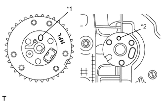
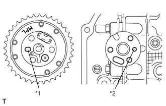
INSTALL CAMSHAFT TIMING EXHAUST GEAR ASSEMBLY LH
Note
Before installation, check that there is no foreign matter on the camshaft timing exhaust gear assembly LH and exhaust camshaft LH.
-
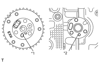
Text in Illustration *1 Knock Hole *2 Knock Pin Install the camshaft timing exhaust gear assembly LH while aligning the knock hole of the camshaft timing exhaust gear assembly LH with the knock pin of the exhaust camshaft LH.
-
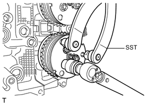
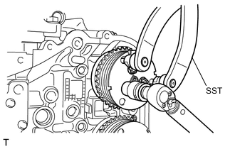
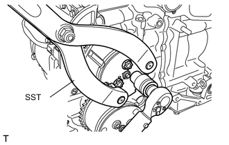
Using SST, hold the camshaft timing exhaust gear assembly LH, and tighten the 3 bolts with a socket "TORX" wrench E16.
- SST
- 09960-10010 ( 09962-01000, 09963-00700 )
- Torque:
- 18 N*m { 184 kgf*cm, 13 ft.*lbf }
-
-
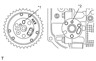
INSTALL CAMSHAFT TIMING INTAKE GEAR ASSEMBLY LH
Note
Before installation, check that there is no foreign matter on the camshaft timing intake gear assembly LH and intake camshaft LH.
-
Text in Illustration *1 Knock Hole *2 Knock Pin Install the camshaft timing exhaust gear assembly LH while aligning the knock hole of the camshaft timing intake gear assembly LH with the knock pin of the intake camshaft LH.
-
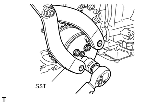
Using SST, hold the camshaft timing intake gear assembly LH, and tighten the 3 bolts with a socket "TORX" wrench E16.
- SST
- 09960-10010 ( 09962-01000, 09963-00700 )
- Torque:
- 18 N*m { 184 kgf*cm, 13 ft.*lbf }
-
-
INSTALL CAMSHAFT TIMING EXHAUST GEAR ASSEMBLY RH
Note
Before installation, check that there is no foreign matter on the camshaft timing exhaust gear assembly RH and exhaust camshaft RH.
-
Text in Illustration *1 Knock Hole *2 Knock Pin Install the camshaft timing intake gear assembly RH while aligning the knock hole of the camshaft timing exhaust gear assembly RH with the knock pin of the exhaust camshaft RH.
-
Using SST, hold the camshaft timing exhaust gear assembly RH, and tighten the 3 bolts with a socket "TORX" wrench E16.
- SST
- 09960-10010 ( 09962-01000, 09963-00700 )
- Torque:
- 18 N*m { 184 kgf*cm, 13 ft.*lbf }
-
-
INSTALL CAMSHAFT TIMING INTAKE GEAR ASSEMBLY RH
Note
Before installation, check that there is no foreign matter on the camshaft timing intake gear assembly RH and intake camshaft RH.
-
Text in Illustration *1 Knock Hole *2 Knock Pin Install the camshaft timing intake gear assembly RH while aligning the knock hole of the camshaft timing intake gear assembly RH with the knock pin of the intake camshaft RH.
-
Using SST, hold the camshaft timing intake gear assembly RH, and tighten the 3 bolts with a socket "TORX" wrench E16.
- SST
- 09960-10010 ( 09962-01000, 09963-00700 )
- Torque:
- 18 N*m { 184 kgf*cm, 13 ft.*lbf }
-
-
INSTALL CRANKSHAFT TIMING GEAR OR SPROCKET
-
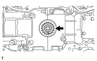
Install the crankshaft timing gear or sprocket.
-
-
INSTALL CHAIN SUB-ASSEMBLY (for Bank 2)
-
INSTALL CHAIN SUB-ASSEMBLY (for Bank 1)
-
INSTALL TIMING CHAIN OR BELT COVER SUB-ASSEMBLY
-
CONNECT ENGINE WIRE
-
INSTALL TIMING CHAIN OR BELT COVER OIL SEAL
-
INSTALL CRANKSHAFT PULLEY
-
INSTALL NO. 1 WATER BY-PASS PIPE (for Manual Transmission)
-
INSTALL NO. 1 WATER BY-PASS PIPE (for Automatic Transmission)
-
INSTALL REAR CYLINDER HEAD PLATE (for Manual Transmission)
-
INSTALL VACUUM PUMP ASSEMBLY (for Automatic Transmission)
-
INSTALL PUMP DRIVE CASE ASSEMBLY
-
INSTALL VALVE LIFTER
-
INSTALL FUEL PUMP ASSEMBLY
-
INSTALL NO. 2 FUEL DELIVERY PIPE
-
INSTALL INTAKE MANIFOLD
-
CONNECT VENTILATION HOSE
-
INSTALL FUEL DELIVERY PIPE SUB-ASSEMBLY
-
INSTALL INJECTOR COVER (for Bank 2)
-
INSTALL INJECTOR COVER (for Bank 1)
-
INSTALL V-RIBBED BELT TENSIONER ASSEMBLY
-
INSTALL NO. 2 IDLER PULLEY SUB-ASSEMBLY
-
INSTALL OIL LEVEL DIPSTICK GUIDE
-
INSTALL GENERATOR ASSEMBLY
-
INSTALL FAN AND GENERATOR V BELT
-
INSTALL BELT GENERATOR COVER
-
INSTALL GENERATOR COVER
-
INSTALL ENGINE HANGER
-
REMOVE ENGINE STAND