CAMSHAFT REMOVAL

PROCEDURE
-
INSTALL ENGINE STAND
-
REMOVE ENGINE HANGER
-
REMOVE GENERATOR COVER
-
REMOVE BELT GENERATOR COVER
-
REMOVE FAN AND GENERATOR V BELT
-
REMOVE GENERATOR ASSEMBLY
-
REMOVE OIL LEVEL DIPSTICK GUIDE
-
REMOVE NO. 2 IDLER PULLEY SUB-ASSEMBLY
-
REMOVE V-RIBBED BELT TENSIONER ASSEMBLY
-
REMOVE INJECTOR COVER (for Bank 2)
-
REMOVE INJECTOR COVER (for Bank 1)
-
REMOVE FUEL DELIVERY PIPE SUB-ASSEMBLY
-
SEPARATE VENTILATION HOSE
-
REMOVE INTAKE MANIFOLD
-
REMOVE NO. 2 FUEL DELIVERY PIPE
-
REMOVE FUEL PUMP ASSEMBLY
-
REMOVE VALVE LIFTER
-
REMOVE PUMP DRIVE CASE ASSEMBLY
-
REMOVE VACUUM PUMP ASSEMBLY (for Automatic Transmission)
-
REMOVE REAR CYLINDER HEAD PLATE (for Manual Transmission)
-
REMOVE NO. 1 WATER BY-PASS PIPE (for Automatic Transmission)
-
REMOVE NO. 1 WATER BY-PASS PIPE (for Manual Transmission)
-
REMOVE CRANKSHAFT PULLEY
-
REMOVE TIMING CHAIN OR BELT COVER OIL SEAL
-
DISCONNECT ENGINE WIRE
-
REMOVE TIMING CHAIN OR BELT COVER SUB-ASSEMBLY
-
REMOVE CHAIN SUB-ASSEMBLY (for Bank 1)
-
REMOVE CHAIN SUB-ASSEMBLY (for Bank 2)
-
ROTATE CRANKSHAFT AND CAMSHAFT
-
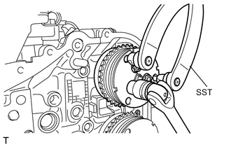
Temporarily install the crankshaft pulley spacer and crankshaft pulley.
-
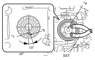
Text in Illustration *a Crankshaft Pulley Pin Hole *b Alignment Mark *c Crankshaft Timing Gear Key Using SST, turn the crankshaft about 200 degrees counterclockwise until the crankshaft pulley pin hole is aligned at the position shown in the illustration.
- SST
- 09960-10010 ( 09962-01000, 09963-01000 )
Note
Do not turn the crankshaft counterclockwise except for a slight adjustment to correctly align the alignment mark. If not, the valves may come into contact with the piston.
Tech Tips
At this time, the alignment mark on the crankshaft timing gear or sprocket and the crankshaft timing gear key are at the positions shown in the illustration.
-
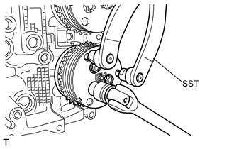
Remove the crankshaft pulley and crankshaft pulley spacer.
-
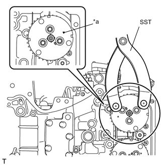
Text in Illustration *a Alignment Mark Using SST, turn the camshaft timing intake gear assembly LH approximately 180°clockwise, and align the alignment mark on the camshaft timing intake gear assembly LH to the position (zero-lift position) shown in the illustration.
- SST
- 09960-10010 ( 09962-01000, 09963-00700 )
Note
After this work, when the intake valve and exhaust valve lift at the same time, the valve heads contact each other, causing the valve stems to bend. To avoid this, do not turn the intake camshaft LH and the exhaust camshaft LH more than the zero-lift range (the range where the camshafts can be turned lightly by hand).
-
-
REMOVE CAMSHAFT TIMING INTAKE GEAR ASSEMBLY RH
-
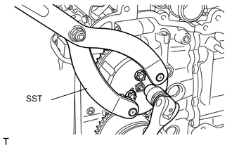
Using SST, hold the camshaft timing intake gear assembly RH and remove the 3 bolts with a "TORX" socket wrench E16.
- SST
- 09960-10010 ( 09962-01000, 09963-00700 )
-
Remove the camshaft timing intake gear assembly RH.
-
-
REMOVE CAMSHAFT TIMING EXHAUST GEAR ASSEMBLY RH
-
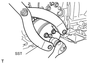
Using SST, hold the camshaft timing exhaust gear assembly RH and remove the 3 bolts with a "TORX" socket wrench E16.
- SST
- 09960-10010 ( 09962-01000, 09963-00700 )
-
Remove the camshaft timing exhaust gear assembly RH.
-
-
REMOVE CAMSHAFT TIMING INTAKE GEAR ASSEMBLY LH
-
Using SST, hold the camshaft timing intake gear assembly LH and remove the 3 bolts with a "TORX" socket wrench E16.
- SST
- 09960-10010 ( 09962-01000, 09963-00700 )
-
Remove the camshaft timing intake gear assembly LH.
-
-
REMOVE CAMSHAFT TIMING EXHAUST GEAR ASSEMBLY LH
-
Using SST, hold the camshaft timing exhaust gear assembly LH and remove the 3 bolts with a "TORX" socket wrench E16.
- SST
- 09960-10010 ( 09962-01000, 09963-00700 )
-
Remove the camshaft timing exhaust gear assembly LH.
-
-
REMOVE IGNITION COIL ASSEMBLY (for Bank 2)
-
REMOVE SPARK PLUG (for Bank 2)
-
REMOVE IGNITION COIL ASSEMBLY (for Bank 1)
-
REMOVE SPARK PLUG (for Bank 1)
-
REMOVE INJECTOR DRIVER BRACKET
-
REMOVE CYLINDER HEAD COVER SUB-ASSEMBLY RH
-
REMOVE CAMSHAFT HOUSING SUB-ASSEMBLY RH
-
REMOVE CYLINDER HEAD COVER SUB-ASSEMBLY LH
-
REMOVE CAMSHAFT HOUSING SUB-ASSEMBLY LH
-
REMOVE CAMSHAFT CAP (for Bank 1)
-
In several steps, uniformly loosen the 12 bolts in the order shown in the illustration, and remove the front camshaft cap RH, intake center camshaft cap RH, intake rear camshaft cap RH, exhaust center camshaft cap RH, and exhaust rear camshaft cap RH.
Tech Tips
Arrange the removed parts in the correct order.
-
-
REMOVE CAMSHAFT RH (for Bank 1)
-
Remove the intake camshaft RH and exhaust camshaft RH from the camshaft housing sub-assembly RH.
-
-
REMOVE CAMSHAFT CAP (for Bank 2)
-
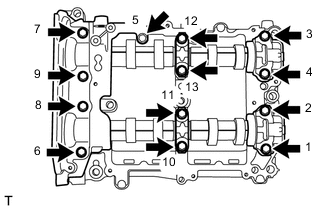
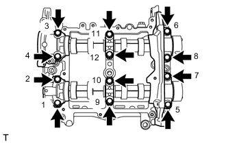
In several steps, uniformly loosen the 13 bolts in the order shown in the illustration, and remove the front camshaft cap LH, intake center camshaft cap LH, intake rear camshaft cap LH, exhaust center camshaft cap LH and exhaust rear camshaft cap LH.
Tech Tips
Arrange the removed parts in the correct order.
-
-
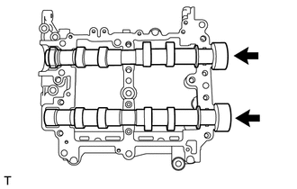
REMOVE CAMSHAFT LH (for Bank 2)
-
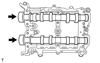
Remove the intake camshaft LH and exhaust camshaft LH from the camshaft housing sub-assembly LH.
-