CYLINDER BLOCK DISASSEMBLY

PROCEDURE
-
REMOVE PISTON SUB-ASSEMBLY WITH CONNECTING ROD
-
Mark each connecting rod cap and piston with a cylinder number.
-
Turn the crankshaft so that the connecting rod cap can be removed.
-
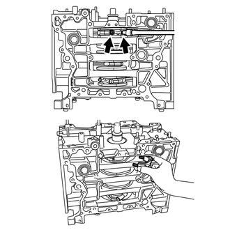
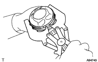
Using a "TORX" socket wrench E14, remove the 2 connecting rod cap bolts and connecting rod cap.
-
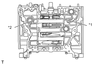
Text in Illustration *1 Crank pin *2 Connecting rod Turn the crankshaft and separate the crank pin from the connecting rod.
Tech Tips
Turn the crankshaft clockwise when removing the No. 1 or No. 3 piston with connecting rod, and turn it counterclockwise when removing the No. 2 or No. 4 piston with connecting rod.
-
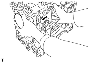
Push the connecting rod in the direction of the arrow, and remove the piston with connecting rod from the cylinder block.
-
-
REMOVE CYLINDER BLOCK SUB-ASSEMBLY (for Bank 1)
Note
Place a cloth to avoid scratching the mating surface of the cylinder block during servicing.
-
Operate the engine stand so that the bank 1 side faces upward.
-
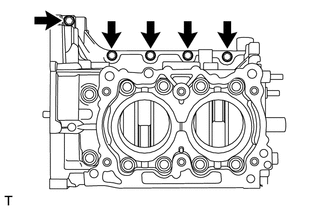
Remove the 5 bolts.
-
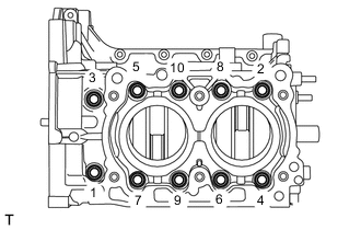
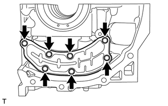
Using a 12 mm socket wrench, loosen the 10 bolts in the order as shown in the illustration.
-
Remove the 10 bolts and cylinder block (for bank 1).
Note
Lift the cylinder block (for bank 1) slightly, and confirm that the crankshaft is remaining on the cylinder block (for bank 2). If the cylinder block (for bank 1) is lifted carelessly when separating, the crankshaft possibly having stuck to cylinder block (for bank 1) may fall off.
-
-
REMOVE CRANKSHAFT
-
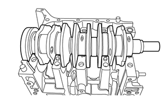
Remove the crankshaft from the cylinder block (for bank 2).
-
-
REMOVE REAR ENGINE OIL SEAL
-
Remove the rear engine oil seal.
-
-
REMOVE O-RING
-
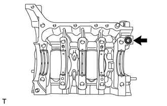
Remove the O-ring from the cylinder block (for bank 2).
-
-
REMOVE CRANKSHAFT BEARING
-
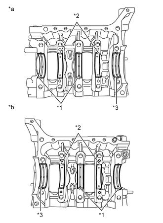
Text in Illustration *1 No. 1 and No. 3 Crankshaft Bearing *2 No. 2 and No. 4 Crankshaft Bearing *3 No. 5 Crankshaft Bearing *a for Bank 1 *b for Bank 2 Remove the crankshaft bearings from the cylinder block (for bank 1) and cylinder block (for bank 2).
Tech Tips
-
Arrange the removed parts in the correct order.
-
Push the bearing at the opposite end to locking lip to remove the bearing.
-
-
-
REMOVE OIL SEPARATOR COVER
-
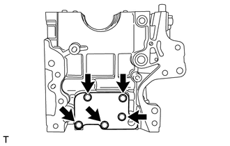
Remove the 7 bolts and oil separator cover from the cylinder block (for bank 1).
-
-
REMOVE CYLINDER BLOCK SUB-ASSEMBLY (for Bank 2)
-
Remove the cylinder block sub-assembly (for bank 2) from the engine stand.
-
-
REMOVE CYLINDER BLOCK PLATE
-
Remove the 5 bolts and cylinder block plate from the cylinder block (for bank 2).
-
-
REMOVE CRANKSHAFT SENSOR HOLDER ASSEMBLY
-
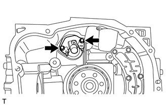
Remove the 2 bolts and crankshaft sensor holder assembly from the cylinder block (for bank 2).
-
-
REMOVE NO. 1 CYLINDER BLOCK TIGHT PLUG
-
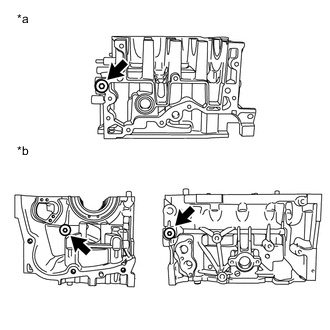
Text in Illustration *a for Bank 1 *b for Bank 2 Remove the 3 No. 1 cylinder block tight plugs from the cylinder block (for bank 1) and cylinder block (for bank 2).
-
-
REMOVE CONNECTING ROD BEARING
-
Remove the connecting rod bearings.
Tech Tips
Arrange the removed parts in the correct order.
-
-
REMOVE PISTON RING SET
Tech Tips
Arrange the removed parts in the correct order.
-
Using a piston ring expander, remove the No. 1 compression ring and No. 2 compression ring in order.
-
Remove the upper oil ring side rail, lower oil ring side rail and oil ring expander in order by hand.
-
-
REMOVE PISTON WITH PIN SUB-ASSEMBLY
-
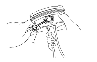
Text in Illustration *1 Protective Tape Using a screwdriver with its tip wrapped in protective tape, remove the piston pin hole snap ring on one end from the piston.
Tech Tips
Be careful not to damage the piston and piston pin by wrapping the tip of the screwdriver with protective tape.
-
Remove the piston pin from the piston.
-
Using a screwdriver with its tip wrapped in protective tape, remove the piston pin hole snap ring on other end from the piston.
Tech Tips
Be careful not to damage the piston and piston pin by wrapping the tip of the screwdriver with protective tape.
-