TIMING CHAIN INSTALLATION

PROCEDURE
-
INSTALL CHAIN SUB-ASSEMBLY (for Bank 2)
Note
Do not allow any foreign matter to adhere onto or to enter into the component parts during installation.
Tech Tips
Apply engine oil to all component parts of the chain sub-assembly.
-
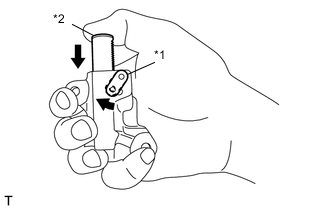
Text in Illustration *1 Link Plate *2 Plunger Move the link plate in the direction of the arrow in the illustration to press in the plunger.
-
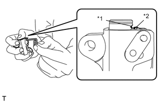
Text in Illustration *1 First notch of the plunger rack *2 Stopper Tooth Insert an approximately 1 mm (0.039 in.) wire or the like into the chain tensioner through the stopper pin hole, and hold the plunger.
Tech Tips
If the stopper pin hole on the link plate and the stopper pin hole on the chain tensioner are not aligned, check that the first notch of the plunger rack is engaged with the stopper tooth. If not engaged, retract the plunger a little so that the first notch of the plunger rack is engaged with the stopper tooth.
-

Text in Illustration *a Alignment Mark *b 25° to 30° Position the alignment marks on the camshaft timing intake gear assembly LH and camshaft timing exhaust gear assembly LH as shown in the illustration.
Note
To avoid damaging the valves, do not turn the camshaft timing intake gear assemblies more than the zero-lift range (the range where camshaft timing intake gear assembles can be turned lightly by hand).
-

Text in Illustration *a Crankshaft Timing Gear Key Check that the alignment mark on the crankshaft timing gear or sprocket is at the position shown in the illustration.
-
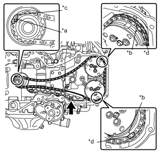
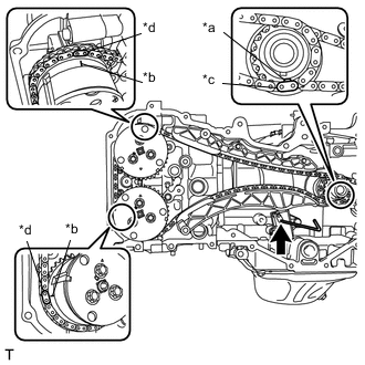
Text in Illustration *a Alignment Mark (Oval) *b Alignment Mark (Engraved Line) *c Mark plate (Grayish Blue) *d Mark plate (Pink) Install the chain sub-assembly in the following order.
-
Align the mark plate (grayish blue) on the chain sub-assembly with the alignment mark (oval) on the crankshaft timing gear or sprocket.
-
Align the mark plate (pink) on the chain sub-assembly with the alignment mark (engraved line) on the camshaft timing exhaust gear assembly LH.
-
Align the mark plate (pink) on the chain sub-assembly with the alignment mark (engraved line) on the camshaft timing intake gear assembly LH.
-
-
Apply engine oil to the bolt.
-
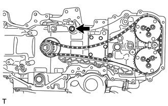
Using a 5 mm hexagon socket wrench, install the No. 1 chain vibration damper with the bolt.
- Torque:
- 6.4 N*m { 65 kgf*cm, 57 in.*lbf }
-
Install a new O-ring to the cylinder block (bank 2).
-
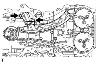
Install the chain tensioner slipper.
-
Install the No. 2 chain tensioner assembly with the 2 bolts.
- Torque:
- 6.4 N*m { 65 kgf*cm, 57 in.*lbf }
-
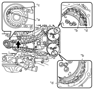
Text in Illustration *a Alignment Mark (Oval) *b Alignment Mark (Engraved Line) *c Mark plate (Grayish Blue) *d Mark plate (Pink) Check that the chain is correctly installed.
-
The mark plate (grayish blue) on the chain sub-assembly is aligned with the alignment mark (oval) on the crankshaft timing gear or sprocket.
-
The mark plate (pink) on the chain sub-assembly is aligned with the alignment mark (engraved line) on the camshaft timing intake gear assembly LH.
-
The mark plate (pink) on the chain sub-assembly is aligned with the alignment mark (engraved line) on the camshaft timing exhaust gear assembly LH.
-
-
Pull out the wire or the like from the No. 2 chain tensioner assembly.
-
Temporarily install the crankshaft pulley spacer and crankshaft pulley.
-
Using SST, turn the crankshaft clockwise to make sure that there are no abnormal conditions.
- SST
- 09960-10010 ( 09962-01000, 09963-01000 )
Note
Be sure to perform this confirmation.
-
-
INSTALL CHAIN SUB-ASSEMBLY (for Bank 1)
Note
Do not allow any foreign matter to adhere onto or to enter into the component parts during installation.
Tech Tips
Apply engine oil to all component parts of the chain sub-assembly.
-
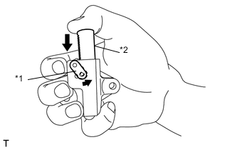
Text in Illustration *1 Link Plate *2 Plunger Move the link plate in the direction of the arrow in the illustration to press in the plunger.
-
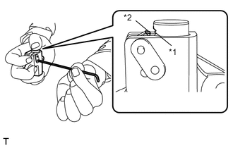
Text in Illustration *1 First notch of the plunger rack *2 Stopper Tooth Insert a 2.5 mm (0.098 in.) hexagon wrench into the No. 1 chain tensioner assembly through the stopper pin hole, and hold the plunger.
Tech Tips
If the stopper pin hole on the link plate and the stopper pin hole on the chain tensioner are not aligned, check that the first notch of the plunger rack is engaged with the stopper tooth. If not engaged, retract the plunger a little so that the first notch of the plunger rack is engaged with the stopper tooth.
-
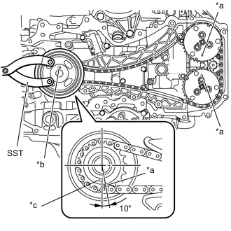
Text in Illustration *a Alignment Mark *b Crankshaft Pulley Pin Hole *c Crankshaft Timing Gear Key Using SST, turn the crankshaft pulley clockwise until the alignment marks on the camshaft timing intake gear assembly LH and the camshaft timing exhaust gear assembly LH, and the crankshaft pulley pin hole are aligned at the positions shown in the illustration.
- SST
- 09960-10010 ( 09962-01000, 09963-01000 )
Tech Tips
At this time, the alignment mark on the crankshaft timing gear or sprocket and the crankshaft timing gear key are at the positions shown in the illustration.
-
Remove the crankshaft pulley and crankshaft pulley spacer.
-
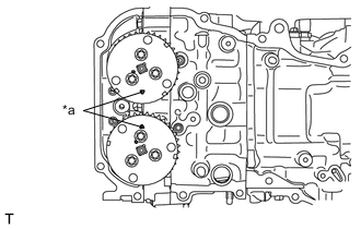
Text in Illustration *a Alignment Mark Align the alignment marks of the camshaft timing intake gear assembly RH and camshaft timing exhaust gear assembly RH as shown in the illustration.
Note
To avoid damaging the valves, do not turn the camshaft timing intake gear assembly RH and camshaft more than the zero-lift range (the range where the camshaft timing intake gear assembles can be turned lightly by hand).
-
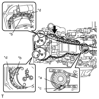
Text in Illustration *a Alignment Mark (Oval) *b Alignment Mark (Engraved Line) *c Mark plate (Grayish Blue) *d Mark plate (Pink) Install the chain sub-assembly in the following order.
-
Align the mark plate (grayish blue) on the chain sub-assembly with the alignment mark (oval) on the crankshaft timing gear or sprocket.
-
Align the mark plate (pink) on the chain sub-assembly with the alignment mark (engraved line) on the camshaft timing intake gear assembly RH.
-
Align the mark plate (pink) on the chain sub-assembly with the alignment mark (engraved line) on the camshaft timing exhaust gear assembly RH.
-
-
Apply engine oil to the bolt.
-
Using a 5 mm hexagon socket wrench, install the No. 1 chain vibration damper with the bolt.
- Torque:
- 6.4 N*m { 65 kgf*cm, 57 in.*lbf }
-
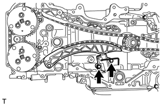
Install the chain tensioner slipper.
-
Install the No. 1 chain tensioner assembly with the 2 bolts.
- Torque:
- 6.4 N*m { 65 kgf*cm, 57 in.*lbf }
-
Text in Illustration *a Alignment Mark (Oval) *b Alignment Mark (Engraved Line) *c Mark plate (Grayish Blue) *d Mark plate (Pink) Check that the chain is correctly installed.
-
The mark plate (grayish blue) on the chain sub-assembly is aligned with the alignment mark (oval) on the crankshaft timing gear or sprocket.
-
The mark plate (pink) on the chain sub-assembly is aligned with the alignment mark (engraved line) on the camshaft timing intake gear assembly RH.
-
The mark plate (pink) on the chain sub-assembly is aligned with the alignment mark (engraved line) on the camshaft timing exhaust gear assembly RH.
-
-
Pull out the hexagon wrench from the No. 1 chain tensioner assembly.
-
Temporarily install the crankshaft pulley spacer and crankshaft pulley.
-
Using SST, turn the crankshaft clockwise to make sure that there are no abnormal conditions.
- SST
- 09960-10010 ( 09962-01000, 09963-01000 )
Note
Be sure to perform this confirmation.
-
Remove the crankshaft pulley and crankshaft pulley spacer.
-
-
INSTALL TIMING CHAIN OR BELT COVER SUB-ASSEMBLY