VALVE CLEARANCE ADJUSTMENT
PROCEDURE
-
REMOVE IGNITION COIL ASSEMBLY
-
REMOVE INJECTOR COVER (for Bank 1)
-
REMOVE INJECTOR DRIVER BRACKET
-
REMOVE CYLINDER HEAD COVER SUB-ASSEMBLY RH
-
REMOVE CYLINDER HEAD COVER SUB-ASSEMBLY LH
-
INSPECT VALVE CLEARANCE
Note
Inspect the valve clearance when the engine is cold.
-
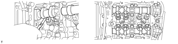
Set the No. 1 cylinder to the TDC/compression.
-
Turn the crankshaft clockwise to align the timing mark on the crankshaft pulley with the indicator of the timing chain cover.
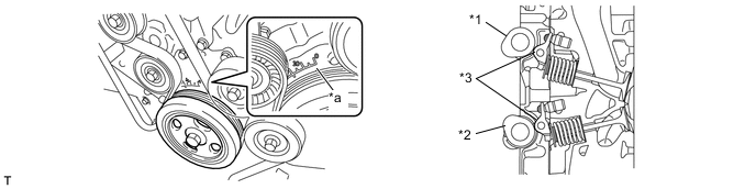
Text in Illustration *1 Intake Camshaft *2 Exhaust Camshaft *3 No. 1 Valve Rocker Arm Sub-assembly - - *a Timing Mark - -
-
-
At this time, check that the intake camshaft and exhaust camshaft do not depress the No. 1 cylinder intake side No. 1 valve rocker arm sub-assembly (intake valve) and exhaust side No. 1 valve rocker arm sub-assembly (exhaust valve).
Tech Tips
If the No. 1 valve rocker arm sub-assembly (valve) is depressed, turn the crank pulley by 360° in order to make the No. 1 cylinder piston at TDC/compression.
-
Inspect the valve clearance indicated in the illustration.
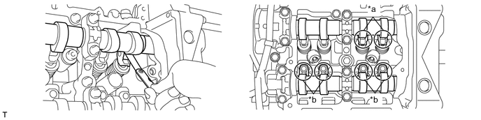
Text in Illustration *a Intake Side *b Exhaust Side -
Measure the clearance between the surface of the cam base circle and the roller surface of the No. 1 valve rocker arm sub-assembly using a feeler gauge.
Standard Calve Clearance (Cold) Intake 0.10 to 0.15 mm (0.00394 to 0.00591 in.) Exhaust 0.20 to 0.24 mm (0.00787 to 0.00945 in.) -
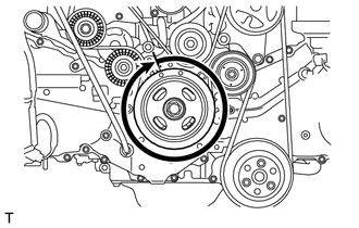
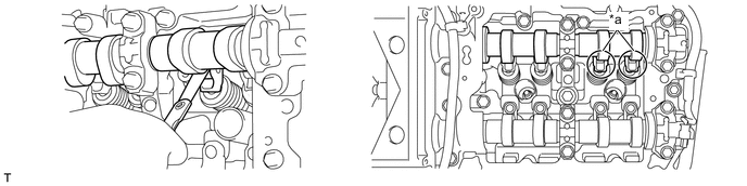
Turn the crank pulley by 360°.
-
Inspect the valve clearance indicated in the illustration.
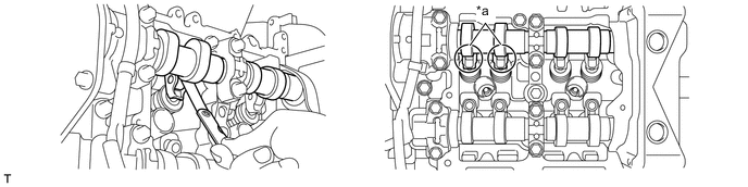
Text in Illustration *a Intake Side - - -
Measure the clearance between the surface of the cam base circle and the roller surface of the No. 1 valve rocker arm sub-assembly using a feeler gauge.
Standard Calve Clearance (Cold) Intake 0.10 to 0.15 mm (0.00394 to 0.00591 in.) -
Turn the crank pulley clockwise, set the No. 2 cylinder at TDC/compression, and then align the timing mark (notch) with 0° position of the timing chain cover.
Text in Illustration *1 Intake Camshaft *2 Exhaust Camshaft *3 No. 1 Valve Rocker Arm Sub-assembly - - *a Timing Mark - - -
At this time, check that the intake camshaft and exhaust camshaft do not depress the No. 2 cylinder intake side No. 1 valve rocker arm sub-assembly (intake valve) and exhaust side No. 1 valve rocker arm sub-assembly (exhaust valve).
Tech Tips
If the No. 1 valve rocker arm sub-assembly (valve) is depressed, turn the crank pulley by 360° in order to make the No. 2 cylinder piston at TDC/compression.
-
Inspect the valve clearance indicated in the illustration.
Text in Illustration *a Intake Side *b Exhaust Side -
Measure the clearance between the surface of the cam base circle and the roller surface of the No. 1 valve rocker arm sub-assembly using a feeler gauge.
Standard Calve Clearance (Cold) Intake 0.10 to 0.15 mm (0.00394 to 0.00591 in.) Exhaust 0.20 to 0.24 mm (0.00787 to 0.00945 in.) -
Turn the crank pulley by 360°.
-
Inspect the valve clearance indicated in the illustration.
Text in Illustration *a Intake Side - - -
Measure the clearance between the surface of the cam base circle and the roller surface of the No. 1 valve rocker arm sub-assembly using a feeler gauge.
Standard Calve Clearance (Cold) Intake 0.10 to 0.15 mm (0.00394 to 0.00591 in.)
-
-
ADJUST VALVE CLEARANCE
-
Remove the camshaft housing sub-assembly.
-
Remove the No. 1 valve rocker arm sub-assemblies.
-
Remove the valve adjusting shims.
-
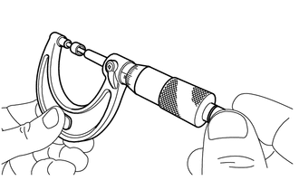
Using a micrometer, measure the thickness of the removed valve adjusting shims.
-
Calculate the thickness of the valve adjusting shim so that the valve clearance comes within the specified values.
Intake Side A = B + [C - 0.13 mm (0.00512 in.)] x 1.69 Exhaust Side A = B + [C - 0.22 mm (0.00866 in.)] x 1.87 A Required valve adjusting shim thickness B Removed valve adjusting shim thickness C Measured valve clearance -
Apply engine oil to the inner face of the valve adjusting shim, and install it to the valve.
Note
Check whether valve adjusting shim can be rotated smoothly on the valve.
-
Install the No. 1 valve rocker arm sub-assemblies.
-
Install the camshaft housing sub-assembly.
-
-
INSTALL CYLINDER HEAD COVER SUB-ASSEMBLY LH
-
INSTALL CYLINDER HEAD COVER SUB-ASSEMBLY RH
-
INSTALL INJECTOR DRIVER BRACKET
-
INSTALL INJECTOR COVER (for Bank 1)
-
INSTALL IGNITION COIL ASSEMBLY