SFI SYSTEM Fuel Pump Control Circuit
DESCRIPTION
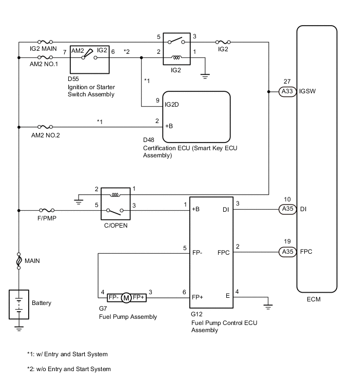
The fuel pump circuit (low pressure side) is comprised of the ECM, fuel pump assembly (low pressure side), and fuel pump control ECU assembly (which operates the fuel pump [low pressure side]). The ECM judges the speed of the fuel pump assembly (low pressure side) based on the engine output. This speed is converted into a loading signal, which is sent to the fuel pump control ECU assembly. The fuel pump control ECU assembly adjusts the fuel pump operating speed (low pressure side), based on the signal sent from the ECM.
WIRING DIAGRAM
CAUTION / NOTICE / HINT
Note
Inspect the fuses for circuits related to this system before performing the following inspection procedure.
PROCEDURE
-
PERFORM ACTIVE TEST USING GTS (CONTROL THE FUEL PUMP/SPEED)
-
Connect the GTS to the DLC3.
-
Turn the ignition switch to ON.
-
Turn the GTS on.
-
Enter the following menus: Powertrain / Engine / Active Test / Control the Fuel Pump/Speed.
-
Check whether the fuel pump operating sound occurs when performing the Active Test on the GTS.
Result Result Proceed to Fuel pump operating sound does not occur A Fuel pump operating sound occurs B
B 
INSPECT FUEL PUMP CONTROL ECU ASSEMBLY (POWER SOURCE VOLTAGE) Click here
A 
-
-
PERFORM ACTIVE TEST USING GTS (CONTROL THE FUEL PUMP)
-
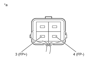
Text in Illustration *a Component without harness connected
(Fuel Pump)
Connect the GTS to the DLC3.
-
Turn the ignition switch to ON.
-
Turn the GTS on.
-
Enter the following menus: Powertrain / Engine / Active Test /Control the Fuel Pump Duty.
-
Measure the voltage according to the value(s) in the table below.
Standard Voltage Tester Connection Condition Specified Condition 3 (FP+) - 4 (FP-) FPC Duty: 25% 3.2 to 4.05 V 3 (FP+) - 4 (FP-) FPC Duty: 80% 8.8 to 12.5 V -
Enter the following menus: Powertrain / Engine / Active Test / Control the Fuel Pump/Speed.
-
Measure the voltage according to the value(s) in the table below.
Standard Voltage Tester Connection Condition Specified Condition 3 (FP+) - 4 (FP-) ON
(FPC Duty: 25%)
9.0 to 14.0 V Tech Tips
-
Be sure to measure the voltage with all the connectors connected.
-
Before performing this inspection, check that the battery voltage is between 11 and 14 V (not depleted).
-
NG
REPLACE FUEL PUMP CONTROL ECU ASSEMBLY Click here
OK
-
-
CHECK HARNESS AND CONNECTOR (ECM - FUEL PUMP CONTROL ECU ASSEMBLY)
-
Disconnect the ECM connector.
-
Disconnect the fuel pump control ECU assembly connector.
-
Measure the resistance according to the value(s) in the table below.
Standard Resistance (Check for open) Tester Connection Condition Specified Condition A35-19 (FPC) - G12-2 (FPC) Always Below 1 Ω Standard Resistance (Check for short) Tester Connection Condition Specified Condition A35-19 (FPC) or G12-2 (FPC) - Body ground Always 10 kΩ or higher
NG 
REPAIR OR REPLACE HARNESS OR CONNECTOR
OK
-
-
REPLACE FUEL PUMP ASSEMBLY
-
Replace the fuel pump assembly Click here.
NEXT
-
-
CHECK CONFIRM WHETHER MALFUNCTION HAS BEEN SUCCESSFULLY REPAIRED
-
Check the fuel pump operation Click here.
OK Malfunction has been repaired successfully.
OK
END
NG
REPLACE ECM Click here
-
-
REPLACE FUEL PUMP CONTROL ECU ASSEMBLY
-
Replace the fuel pump control ECU assembly Click here.
NEXT
-
-
CHECK CONFIRM WHETHER MALFUNCTION HAS BEEN SUCCESSFULLY REPAIRED
-
Check the fuel pump operation Click here.
OK Malfunction has been repaired successfully.
OK
END
NG
REPLACE ECM Click here
-
-
INSPECT FUEL PUMP CONTROL ECU ASSEMBLY (POWER SOURCE VOLTAGE)
-
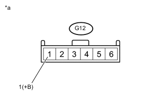
Text in Illustration *a Front view of wire harness connector:
(to fuel pump control ECU)
Disconnect the fuel pump control ECU assembly connector.
-
Turn the ignition switch to ON.
-
Measure the voltage according to the value(s) in the table below.
Standard Voltage Tester Connection Condition Specified Condition G12-1 (+B) - Body ground Ignition switch ON 11 to 14 V
NG
CHECK HARNESS AND CONNECTOR (C/OPEN RELAY - FUEL PUMP CONTROL ECU ASSEMBLY) Click here
OK
-
-
CHECK HARNESS AND CONNECTOR (FUEL PUMP - FUEL PUMP CONTROL ECU ASSEMBLY)
-
Disconnect the fuel pump connector.
-
Disconnect the fuel pump control ECU assembly connector.
-
Measure the resistance according to the value(s) in the table below.
Standard Resistance (Check for open) Tester Connection Condition Specified Condition G7-4 (FP-) - G12-5 (FP-) Always Below 1 Ω G7-3 (FP+) - G12-6 (FP+) Always Below 1 Ω Standard Resistance (Check for short) Tester Connection Condition Specified Condition G7-4 (FP-) or G12-5 (FP-) - Body ground Always 10 kΩ or higher G7-3 (FP+) or G12-6 (FP+) - Body ground Always 10 kΩ or higher
NG
REPAIR OR REPLACE HARNESS OR CONNECTOR
OK
-
-
INSPECT FUEL PUMP ASSEMBLY
-
Inspect fuel pump assembly Click here.
NG
REPLACE FUEL PUMP ASSEMBLY Click here
OK
-
-
CHECK HARNESS AND CONNECTOR (FUEL PUMP CONTROL ECU ASSEMBLY - ECM)
-
Disconnect the ECM connector.
-
Disconnect the fuel pump control ECU assembly connector.
-
Measure the resistance according to the value(s) in the table below.
Standard Resistance (Check for open) Tester Connection Condition Specified Condition A35-19 (FPC) - G12-2 (FPC) Always Below 1 Ω G12-4 (E)- Body ground Always Below 1 Ω Standard Resistance (Check for short) Tester Connection Condition Specified Condition A35-19 (FPC) or G12-2 (FPC) - Body ground Always 10 kΩ or higher
NG
REPAIR OR REPLACE HARNESS OR CONNECTOR
OK
-
-
REPLACE FUEL PUMP CONTROL ECU ASSEMBLY
-
Replace the fuel pump control ECU assembly Click here.
NEXT
-
-
CHECK CONFIRM WHETHER MALFUNCTION HAS BEEN SUCCESSFULLY REPAIRED
-
Check the fuel pump operation Click here.
OK Malfunction has been repaired successfully.
OK
END
NG
REPLACE ECM Click here
-
-
CHECK HARNESS AND CONNECTOR (C/OPEN RELAY - FUEL PUMP CONTROL ECU ASSEMBLY)
-
Remove the C/OPEN relay from the engine room relay block assembly.
-
Disconnect the fuel pump control ECU assembly connector.
-
Measure the resistance according to the value(s) in the table below.
Standard Resistance (Check for open) Tester Connection Condition Specified Condition C/OPEN relay terminal 3 - G12-1 (+B) Always Below 1 Ω C/OPEN relay terminal 1 - Body ground Always Below 1 Ω Standard Resistance (Check for short) Tester Connection Condition Specified Condition C/OPEN relay terminal 3 or G12-1 (+B) - Body ground Always 10 kΩ or higher
NG
REPAIR OR REPLACE HARNESS OR CONNECTOR
OK
-
-
INSPECT TERMINAL VOLTAGE (C/OPEN RELAY)
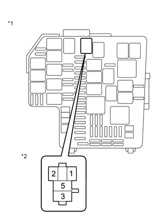
Text in Illustration *1 Engine Room Relay Block Assembly *2 C/OPEN Relay Terminal
-
Remove the C/OPEN relay from the engine room relay block assembly.
-
Measure the voltage according to the value(s) in the table below.
Standard Voltage Tester Connection Condition Specified Condition C/OPEN relay terminal 5 - Body ground IG ON 11 to 14 V
NG
GO TO ECM POWER SOURCE CIRCUIT Click here
OK
-
-
CHECK HARNESS AND CONNECTOR (C/OPEN RELAY - ECM - IG2 RELAY)
-
Disconnect the ECM connector.
-
Remove the C/OPEN relay and IG2 relay from the engine room relay block assembly.
-
Measure the resistance according to the value(s) in the table below.
Standard Resistance (Check for open) Tester Connection Condition Specified Condition C/OPEN relay terminal 2 - A33-27 (IGSW) Always Below 1 Ω C/OPEN relay terminal 2 - IG2 relay terminal 3 Always Below 1 Ω Standard Resistance (Check for short) Tester Connection Condition Specified Condition C/OPEN relay terminal 2, A33-27 (IGSW) or IG2 relay terminal 3 - Body ground Always 10 kΩ or higher
OK
REPLACE ECM Click here
NG
REPAIR OR REPLACE HARNESS OR CONNECTOR
-