SFI SYSTEM VC Output Circuit
DESCRIPTION
The ECM constantly generates 5 V power from the battery voltages supplied to the +B terminal and +B2 terminal to operate the microprocessor. The ECM also provides this power to the sensors through the VC output circuit.
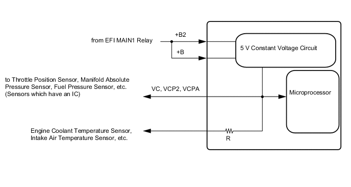
When the VC circuit is short-circuited, the sensors that are supplied with power through the VC circuit are deactivated because the power is not supplied from the VC circuit.
CAUTION / NOTICE / HINT
Note
Inspect the fuses for circuits related to this system before performing the following procedure.
PROCEDURE
-
CHECK CONNECTION BETWEEN GTS AND ECM
-
Connect the GTS to the DLC3.
-
Turn the ignition switch to ON.
-
Turn the GTS on.
-
Check for communication between the GTS and ECM.
Tech Tips
Checking the Data List for "Engine" is possible.
Result Result Proceed to Communication is not possible A Communication is possible B
B 
PROCEED TO NEXT SUSPECTED AREA SHOWN IN PROBLEM SYMPTOMS TABLE Click here
A 
-
-
CHECK TERMINAL VOLTAGE (ECM)
-
Turn the ignition switch to ON.
-
Measure the voltage according to the value(s) in the table below.
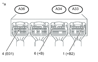
Standard Voltage Tester Connection Switch Condition Specified Condition A34-6 (+B) - A36-4 (E01) Ignition switch ON 11 to 14 V A33-1 (+B2) - A36-4 (E01) Ignition switch ON 11 to 14 V Tech Tips
If the result is not as specified, the system may not be activated due to no power supply to the ECM terminals +B and +B2.
NG
CHECK ECM POWER SOURCE CIRCUIT Click here
OK
-
-
CHECK SHORT CIRCUIT (THROTTLE POSITION SENSOR)
-
Disconnect the throttle with motor body assembly connector.
-
Turn the ignition switch to ON.
-
Turn the GTS on.
-
Check the communication between the GTS and ECM.
Tech Tips
Checking the Data List for "Engine" is possible.
Result Result Proceed to Communication is not possible A Communication is possible B
B
REPLACE THROTTLE WITH MOTOR BODY ASSEMBLY Click here
A
-
-
CHECK SHORT CIRCUIT (MANIFOLD ABSOLUTE PRESSURE SENSOR)
-
Disconnect the manifold absolute pressure sensor connector.
-
Turn the ignition switch to ON.
-
Turn the GTS on.
-
Check the communication between the GTS and ECM.
Tech Tips
Checking the Data List for "Engine" is possible.
Result Result Proceed to Communication is not possible A Communication is possible B
B
REPLACE MANIFOLD ABSOLUTE PRESSURE SENSOR Click here
A
-
-
CHECK SHORT CIRCUIT (FUEL PRESSURE SENSOR)
-
Disconnect the fuel pressure sensor connector.
-
Turn the ignition switch to ON.
-
Turn the GTS on.
-
Check the communication between the GTS and ECM.
Tech Tips
Checking the Data List for "Engine" is possible.
Result Result Proceed to Communication is not possible A Communication is possible B
B
REPLACE FUEL PRESSURE SENSOR Click here
A
-
-
CHECK SHORT CIRCUIT (CRANKSHAFT POSITION SENSOR))
-
Disconnect the crankshaft position sensor connector.
-
Turn the ignition switch to ON.
-
Turn the GTS on.
-
Check the communication between the GTS and ECM.
Tech Tips
Checking the Data List for "Engine" is possible.
Result Result Proceed to Communication is not possible A Communication is possible B
B
REPLACE CRANKSHAFT POSITION SENSOR Click here
A
-
-
CHECK SHORT CIRCUIT (ACCELERATOR PEDAL SENSOR ASSEMBLY)
-
Disconnect the accelerator pedal sensor assembly connector.
-
Turn the ignition switch to ON.
-
Turn the GTS on.
-
Check the communication between the GTS and ECM.
Tech Tips
Checking the Data List for "Engine" is possible.
Result Result Proceed to Communication is not possible A Communication is possible B
B
REPLACE ACCELERATOR PEDAL SENSOR ASSEMBLY Click here
A
-
-
CHECK SHORT CIRCUIT (BATTERY CURRENT SENSOR ASSEMBLY)
-
Disconnect the battery current sensor assembly connector.
-
Turn the ignition switch to ON.
-
Turn the GTS on.
-
Check the communication between the GTS and ECM.
Tech Tips
Checking the Data List for "Engine" is possible.
Result Result Proceed to Communication is not possible (w/ EVAP System) A Communication is not possible (w/o EVAP System) B Communication is possible C
B 
CHECK HARNESS AND CONNECTOR (EACH SENSOR - ECM) Click here
C
REPLACE BATTERY CURRENT SENSOR ASSEMBLY Click here
A
-
-
CHECK SHORT CIRCUIT (CANISTER PUMP MODULE)
-
Disconnect the canister pump module connector.
-
Turn the ignition switch to ON.
-
Turn the GTS on.
-
Check the communication between the GTS and ECM.
Tech Tips
Checking the Data List for "Engine" is possible.
Result Result Proceed to Communication is not possible A Communication is possible B
B
REPLACE CANISTER PUMP MODULE Click here
A
-
-
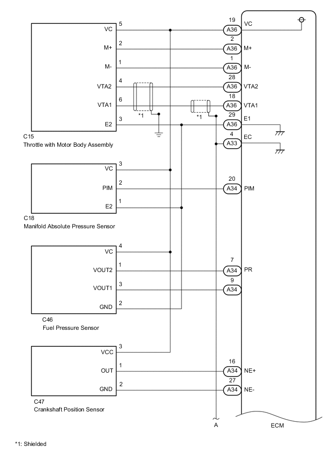
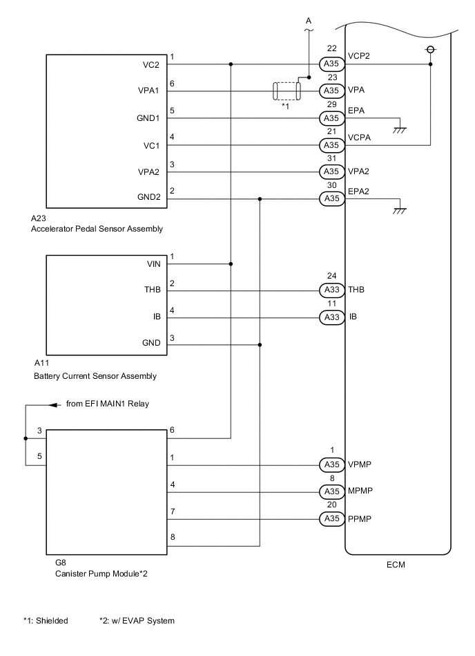
CHECK HARNESS AND CONNECTOR (EACH SENSOR - ECM)
-
Disconnect the throttle with motor body assembly connector.
-
Disconnect the manifold absolute pressure sensor connector.
-
Disconnect the fuel pressure sensor connector.
-
Disconnect the crankshaft position sensor connector.
-
Disconnect the accelerator pedal sensor assembly connector.
-
Disconnect the battery current sensor assembly connector.
-
Disconnect the canister pump module connector.*
*: w/ EVAP System
-
Disconnect the ECM connectors.
-
Measure the resistance according to the value(s) in the table below.
Standard Resistance Tester Connection Condition Specified Condition A36-19 (VC) - Body ground Always 10 kΩ or higher A35-22 (VCP2) - Body ground Always 10 kΩ or higher A35-21 (VCPA) - Body ground Always 10 kΩ or higher
OK
REPLACE ECM Click here
NG
REPAIR OR REPLACE HARNESS OR CONNECTOR
-