SFI SYSTEM, Diagnostic DTC:P2401, P2402, P2419, P2420
| DTC Code | DTC Name |
|---|---|
| P2401 | Evaporative Emission System Leak Detection Pump Control Circuit Low |
| P2402 | Evaporative Emission Leak Detection Pump Stuck ON |
| P2419 | Evaporative Emission System Switching Valve Control Circuit Low |
| P2420 | Evaporative Emission Pressure Switching Valve Stuck OFF |
DTC SUMMARY
| DTC No. | Monitoring Item | Malfunction Detection Condition | Trouble Area | Detection Timing | Detection Logic |
|---|---|---|---|---|---|
| P2401 | Leak detection pump stuck OFF | P2401, P2402, P2419 and P2420 stored when one of following conditions met during EVAP monitor:
|
|
Ignition switch ON or while EVAP monitor | 1 trip |
| P2402 | Leak detection pump stuck ON | ||||
| P2419 | Vent valve circuit low | ||||
| P2420 | Vent valve circuit high |
DESCRIPTION
The description can be found in EVAP (Evaporative Emission) System Click here.
MONITOR DESCRIPTION
While the ECM monitors the EVAP system, it also monitors the status of the leak detection pump and the vent valve within the canister pump module. If the ECM detects an abnormality in the leak detection pump or vent valve operational statuses, the ECM stores the DTC, and illuminates the MIL.
CONFIRMATION DRIVING PATTERN
Note
-
The Evaporative System Check (Automatic Mode) consists of 5 steps performed automatically by the GTS. It takes a maximum of approximately 24 minutes.
-
Do not perform the Evaporative System Check when the fuel tank is more than 90% full because the cut-off valve may be closed, making the fuel tank leak check unavailable.
-
Do not run the engine during this operation.
-
When the temperature of the fuel is 35°C (95°F) or more, a large amount of vapor forms and any check results become inaccurate. When performing the Evaporative System Check, keep the fuel temperature below 35°C (95°F) and the coolant temperature below 45°C (113°F).
-
Connect the GTS to the DLC3.
-
Turn the ignition switch to ON and turn the GTS on.
-
Clear DTCs (even if no DTCs are stored, perform the clear DTC procedure) Click here.
-
Turn the ignition switch off and wait for at least 30 seconds.
-
Turn the ignition switch to ON and turn the GTS on.
-
Enter the following menus: Powertrain / Engine / Utility / Evaporative System Check / Automatic Mode.
-
After the "Evaporative System Check" is completed, check for All Readiness by entering the following menus: Powertrain / Engine / Utility / All readiness.
-
Input the DTC: P2401, P2402, P2419 or P2420.
-
Check the DTC judgment result.
GTS Display Description NORMAL
-
DTC judgment completed
-
System normal
ABNORMAL
-
DTC judgment completed
-
System abnormal
INCOMPLETE
-
DTC judgment not completed
-
Perform driving pattern after confirming DTC enabling conditions
N/A
-
Unable to perform DTC judgment
-
Number of DTCs which do not fulfill DTC preconditions has reached ECU memory limit
Tech Tips
-
If the judgment result shows NORMAL, the system is normal.
-
If the judgment result shows ABNORMAL, the system has a malfunction.
-
-
If the judgment result is INCOMPLETE or N/A and no pending DTC is output, perform a universal trip and check for permanent DTCs Click here.
Tech Tips
-
If a permanent DTC is output, the system is malfunctioning.
-
If no permanent DTC is output, the system is normal.
-
WIRING DIAGRAM
Refer to DTC P0451 Click here.
CAUTION / NOTICE / HINT
Note
-
Do not disassemble the canister pump module.
-
Inspect the fuses for circuits related to this system before performing the following inspection procedure.
PROCEDURE
-
INSPECT CANISTER PUMP MODULE (POWER SOURCE)
-
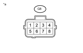
Text in Illustration *a Component without harness connected
(Canister Pump Module)
Turn the ignition switch off.
-
Disconnect the canister pump module connector.
-
Measure the resistance according to the value(s) in the table below.
Standard Voltage Tester Connection Switch Condition Specified Condition G8-3 - Body ground Ignition switch ON 11 to 14 V G8-5 - Body ground Ignition switch ON 11 to 14 V
NG 
INSPECT RELAY (EFI MAIN1) Click here
OK 
-
-
CHECK HARNESS AND CONNECTOR (CANISTER PUMP MODULE - ECM)
-
Turn the ignition switch off.
-
Disconnect the canister pump module connector.
-
Disconnect the ECM connector.
-
Measure the resistance according to the value(s) in the table below.
Standard Resistance (Check for open) Tester Connection Condition Specified Condition A35-8 (MPMP) - G8-4 Always Below 1 Ω A35-1 (VPMP) - G8-1 Always Below 1 Ω Standard Resistance (Check for short) Tester Connection Condition Specified Condition A35-8 (MPMP) or G8-4 - Body ground Always 10 kΩ or higher A35-1 (VPMP) or G8-1 - Body ground Always 10 kΩ or higher
NG 
REPAIR OR REPLACE HARNESS OR CONNECTOR
OK
-
-
INSPECT CANISTER PUMP MODULE
-
Inspect the canister pump module Click here.
OK
CHECK INTERMITTENT PROBLEMS Click here
NG
REPLACE CANISTER PUMP MODULE Click here
-
-
INSPECT RELAY (EFI MAIN1)
-
Inspect the EFI MAIN1 relay Click here.
NG
REPLACE RELAY (EFI MAIN1)
OK
-
-
CHECK HARNESS AND CONNECTOR (CANISTER PUMP MODULE - EFI MAIN1 RELAY)
-
Turn the ignition switch off.
-
Remove EFI MAIN1 relay from the engine room relay block assembly.
-
Measure the resistance according to the value(s) in the table below.
Standard Resistance (Check for open) Tester Connection Condition Specified Condition G8-3 - EFI MAIN1 relay terminal 3 Always Below 1 Ω G8-5 - EFI MAIN1 relay terminal 3 Always Below 1 Ω Standard Resistance (Check for short) Tester Connection Condition Specified Condition G8-3 or EFI MAIN1 relay terminal 3 - Body ground Always 10 kΩ or higher G8-5 or EFI MAIN1 relay terminal 3 - Body ground Always 10 kΩ or higher
OK
GO TO ECM POWER SOURCE CIRCUIT Click here
NG
REPAIR OR REPLACE HARNESS OR CONNECTOR
-