SFI SYSTEM, Diagnostic DTC:P2101, P2102, P2103
| DTC Code | DTC Name |
|---|---|
| P2101 | Throttle Actuator Control Motor Circuit Range/Performance |
| P2102 | Throttle Actuator Control Motor Circuit Low |
| P2103 | Throttle Actuator Control Motor Circuit High |
DESCRIPTION
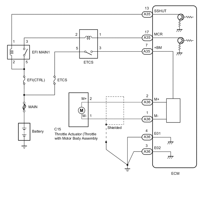
The throttle actuator is operated by the ECM and opens and closes the throttle valve using gears.
The opening angle of the throttle valve is detected by the throttle position sensor, which is mounted on the throttle with motor body assembly. The throttle position sensor provides feedback to the ECM. This feedback allows the ECM to appropriately control the throttle actuator and monitor the throttle opening angle as the ECM responds to driver inputs.
Tech Tips
This Electronic Throttle Control System (ETCS) does not use a throttle cable.
| DTC No. | DTC Detection Condition | Trouble Area |
|---|---|---|
| P2101 | One of the following conditions is met (1 trip detection logic):
|
|
| P2102 | ECM is turning ETCS relay on but throttle actuator power supply voltage is 5 V or less. (1 trip detection logic) |
|
| P2103 | ECM is turning ETCS relay off but throttle actuator power supply voltage is 5 V or more. (1 trip detection logic) |
|
MONITOR DESCRIPTION
The ECM monitors the electrical current through the electronic actuator, and detects malfunctions and open circuits in the throttle actuator based on this value. If the current is outside the standard range, the ECM determines that there is a malfunction in the throttle actuator. In addition, if the throttle valve does not function properly (for example, stuck on), the ECM determines that there is a malfunction. The ECM then illuminates the MIL and stores a DTC.
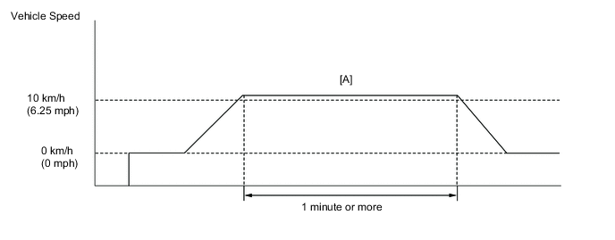
CONFIRMATION DRIVING PATTERN
-
-
Connect the GTS to the DLC3.
-
Turn the ignition switch to ON and turn the GTS on.
-
Clear DTCs (even if no DTCs are stored, perform the clear DTC operation) Click here.
-
Turn the ignition switch off and wait for at least 30 seconds.
-
Turn the ignition switch to ON and turn the GTS on.
-
Start the engine and warm it up until the engine coolant temperature reaches 75°C (167°F) or higher.
-
Depress the accelerator pedal fully and release the accelerator pedal.
-
Drive the vehicle at 10 km/h (6.25 mph) or more for 1 minute or more [A].
CAUTION:
When performing the confirmation driving pattern, obey all speed limits and traffic laws.
-
Enter the following menus: Powertrain / Engine / Trouble Codes.
-
Read pending DTCs.
Tech Tips
-
If a pending DTC is output, the system is malfunctioning.
-
If a pending DTC is not output, perform the following procedure.
-
-
Enter the following menus: Powertrain / Engine / Utility / All Readiness.
-
Input the DTC: P2101, P2102 or P2103.
-
Check the DTC judgment result.
GTS Display Description NORMAL
-
DTC judgment completed
-
System normal
ABNORMAL
-
DTC judgment completed
-
System abnormal
INCOMPLETE
-
DTC judgment not completed
-
Perform driving pattern after confirming DTC enabling conditions
N/A
-
Unable to perform DTC judgment
-
Number of DTCs which do not fulfill DTC preconditions has reached ECU memory limit
Tech Tips
-
If the judgment result shows NORMAL, the system is normal.
-
If the judgment result shows ABNORMAL, the system has a malfunction.
-
-
If the test result is INCOMPLETE or N/A and no DTC is output, perform a universal trip and check for permanent DTCs Click here.
Tech Tips
-
If a permanent DTC is output, the system is malfunctioning.
-
If no permanent DTC is output, the system is normal.
-
FAIL-SAFE
When either of these DTCs or other DTCs relating to ETCS (Electronic Throttle Control System) malfunctions are stored, the ECM enters fail-safe mode. During fail-safe mode, the ECM cuts the current to the throttle actuator, and the throttle valve is returned to a fully closed throttle angle by the return spring. The ECM then adjusts the engine output by controlling the fuel injection (intermittent fuel-cut) and ignition timing, in accordance with the accelerator pedal opening angle, to allow the vehicle to continue running at a minimal speed. If the accelerator pedal is depressed firmly and gently, the vehicle can be driven slowly.
Fail-safe mode continues until a pass condition is detected, and the ignition switch is then turned off.
WIRING DIAGRAM
CAUTION / NOTICE / HINT
Note
Inspect the fuses for circuits related to this system before performing the following inspection procedure.
Tech Tips
-
Read freeze frame data using the GTS. The ECM records vehicle and driving condition information as freeze frame data the moment a DTC is stored. When troubleshooting, freeze frame data can help determine if the vehicle was moving or stationary, if the engine was warmed up or not, if the air fuel ratio was lean or rich, and other data from the time the malfunction occurred.
-
The throttle actuator current (Throttle Motor Current) and the throttle actuator duty ratio (Throttle Motor Duty (Open) / Throttle Motor Duty (Close)) can be read using the GTS. However, the ECM shuts off the throttle actuator current when the electronic throttle control system malfunctions.
PROCEDURE
-
INSPECT TERMINAL VOLTAGE (POWER SOURCE OF THROTTLE WITH MOTOR BODY ASSEMBLY)
-
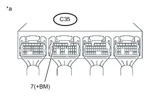
Text in Illustration *a Component with harness connected
(ECM)
Measure the voltage according to the value(s) in the table below.
Standard Voltage Tester Connection Condition Specified Condition C35-7 (+BM) - Body ground Ignition switch ON 11 to 14 V
NG 
INSPECT RELAY (ETCS) Click here
OK 
-
-
INSPECT THROTTLE WITH MOTOR BODY ASSEMBLY (RESISTANCE OF THROTTLE ACTUATOR)
-
Inspect the throttle with motor body assembly Click here.
NG 
REPLACE THROTTLE WITH MOTOR BODY ASSEMBLY Click here
OK
-
-
CHECK HARNESS AND CONNECTOR (THROTTLE WITH MOTOR BODY ASSEMBLY - ECM)
-
Disconnect the throttle with motor body assembly connector.
-
Disconnect the ECM connector.
-
Measure the resistance according to the value(s) in the table below.
Standard Resistance (Check for open) Tester Connection Condition Specified Condition A36-2 (M+) - C15-2 (M+) Always Below 1 Ω A36-1 (M-) - C15-1 (M-) Always Below 1 Ω Standard Resistance (Check for short) Tester Connection Condition Specified Condition A36-2 (M+) or C15-2 (M+) - Body ground Always 10 kΩ or higher A36-1 (M-) or C15-1 (M-) - Body ground Always 10 kΩ or higher
NG
REPAIR OR REPLACE HARNESS OR CONNECTOR
OK
-
-
INSPECT THROTTLE WITH MOTOR BODY ASSEMBLY (VISUALLY CHECK THROTTLE VALVE)
-
Check for foreign objects between the throttle valve and the housing.
OK No foreign objects between the throttle valve and housing.
NG
REMOVE FOREIGN OBJECT
OK
-
-
INSPECT THROTTLE WITH MOTOR BODY ASSEMBLY (THROTTLE VALVE)
-
Check if the throttle valve opens and closes smoothly.
OK Throttle valve opens and closes smoothly.
OK
REPLACE ECM Click here
NG
REPLACE THROTTLE WITH MOTOR BODY ASSEMBLY Click here
-
-
INSPECT RELAY (ETCS)
-
Inspect the ETCS relay Click here.
NG
REPLACE RELAY (ETCS)
OK
-
-
CHECK HARNESS AND CONNECTOR (ETCS RELAY - EFI MAIN1 RELAY - BATTERY)
-
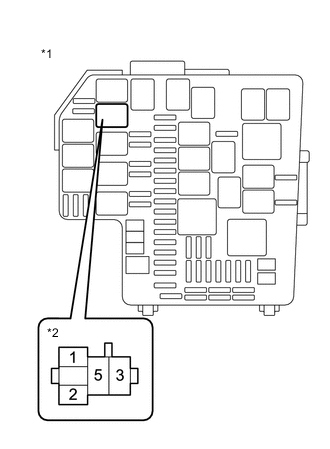
Text in Illustration *1 Engine room relay block assembly *2 ETCS relay terminal Remove the ETCS relay from the engine room relay block assembly.
-
Measure the voltage according to the value(s) in the table below.
Standard Voltage Tester Connection Condition Specified Condition 5 (ETCS relay holder) - Body ground Always 11 to 14 V 2 (ETCS relay holder) - Body ground Ignition switch ON 11 to 14 V Result Result Proceed to Normal A ETCS relay terminal 5 is abnormal. B ETCS relay terminal 2 is abnormal. C
B
REPAIR OR REPLACE HARNESS OR CONNECTOR
C
INSPECT RELAY (EFI MAIN1) Click here
A
-
-
CHECK HARNESS AND CONNECTOR (ECM - ETCS RELAY)
-
Remove the ETCS relay from the engine room relay block assembly.
-
Disconnect the ECM connector.
-
Measure the resistance according to the value(s) in the table below.
Standard Resistance (Check for open) Tester Connection Condition Specified Condition A35-17 (MCR) - ETCS relay terminal 1 Always Below 1 Ω A35-7 (+BM) - ETCS relay terminal 3 Always Below 1 Ω Standard Resistance (Check for short) Tester Connection Condition Specified Condition A35-17 (MCR) or ETCS relay terminal 1 - Body ground Always 10 kΩ or higher A35-7 (+BM) or ETCS relay terminal 3 - Body ground Always 10 kΩ or higher
NG
REPAIR OR REPLACE HARNESS OR CONNECTOR
OK
-
-
INSPECT RELAY (EFI MAIN1)
-
Inspect EFI MAIN1 relay Click here.
NG
REPLACE RELAY (EFI MAIN1)
OK
-
-
CHECK HARNESS AND CONNECTOR (ETCS RELAY - EFI MAIN1 RELAY)
-
Remove the ETCS relay from the engine room relay block assembly.
-
Remove the EFI MAIN1 relay from the engine room relay block assembly.
-
Measure the resistance according to the value(s) in the table below.
Standard Resistance (Check for open) Tester Connection Condition Specified Condition EFI MAIN1 relay terminal 3 - ETCS relay terminal 2 Always Below 1 Ω Standard Resistance (Check for short) Tester Connection Condition Specified Condition EFI MAIN1 relay terminal 3 or ETCS relay terminal 2 - Body ground Always 10 kΩ or higher
OK
CHECK ECM POWER SOURCE CIRCUIT Click here
NG
REPAIR OR REPLACE HARNESS OR CONNECTOR
-