SFI SYSTEM, Diagnostic DTC:P0420
| DTC Code | DTC Name |
|---|---|
| P0420 | Catalyst System Efficiency Below Threshold (Bank 1) |
DESCRIPTION
The ECM uses sensors mounted in front of and behind the Three-Way Catalytic Converter (TWC) to monitor its efficiency.
The first sensor, the air fuel ratio sensor, sends pre-catalyst information to the ECM. The second sensor, the heated oxygen sensor, sends post-catalyst information to the ECM.
In order to detect any deterioration in the three-way catalytic converter, the ECM calculates the oxygen storage capacity of the three-way catalytic converter. This calculation is based on the voltage output of the heated oxygen sensor.
The ECM uses the oxygen storage capacity value to determine the state of the three-way catalytic converter. If any deterioration has occurred, the ECM illuminates the MIL and stores the DTC.
This system determines the deterioration of the entire catalyst system (including the front and rear catalysts), by using the oxygen storage capacity value of the front catalyst, that is more sensitive than the rear catalyst, as the representative value. Therefore, be sure to replace the front and rear catalysts together when catalyst replacement is necessary.
| DTC No. | DTC Detection Condition | Trouble Area |
|---|---|---|
| P0420 | Diagnostic value is more than the standard value. (2 trip detection logic) |
|
CATALYST LOCATION
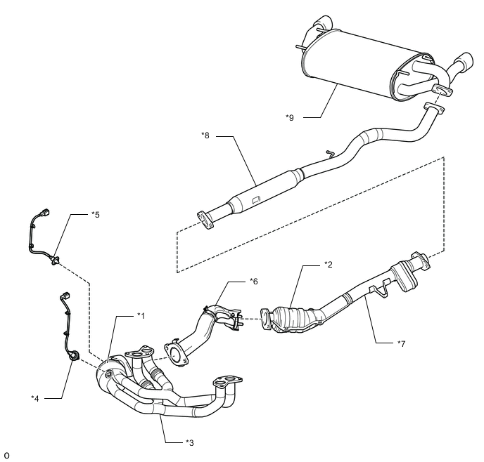
| *1 | TWC: Front Catalyst | *2 | TWC: Rear Catalyst |
| *3 | Exhaust Manifold | *4 | Air Fuel Ratio Sensor |
| *5 | Heated Oxygen Sensor | *6 | Front Exhaust Pipe Sub-Assembly |
| *7 | Front Exhaust Pipe Assembly | *8 | Center Exhaust Pipe Assembly |
| *9 | Tail Exhaust pipe Assembly | - | - |
MONITOR DESCRIPTION
The ECM uses diagnostic values to determine deterioration of the catalyst. If the diagnostic value exceeds a specified value, the catalyst is considered deteriorated, and the DTC is stored.
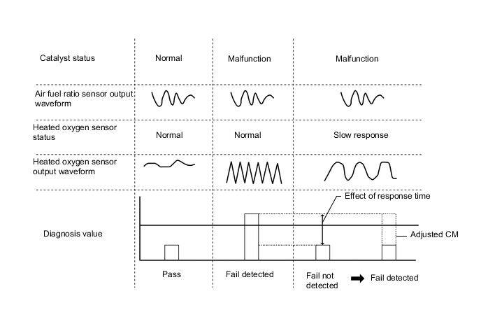
The diagnostic values are based upon the catalyst monitor value (CM) calculated by changes in the air fuel ratio sensor lambda and changes in the heated oxygen sensor output voltage, and in the response rate calculated from the heated oxygen sensor response time.
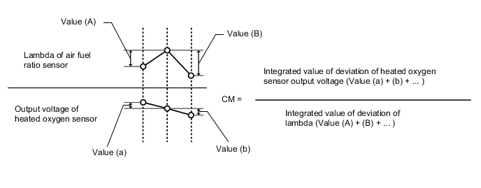
*: Diagnostic Value = CM X (1 + Response rate)
CONFIRMATION DRIVING PATTERN
-
Connect the GTS to the DLC3.
-
Turn the ignition switch to ON and turn the GTS on.
-
Clear DTCs (even if no DTCs are stored, perform the clear DTC operation) Click here.
-
Turn the ignition switch off and wait for at least 30 seconds.
-
Turn the ignition switch to ON and turn the GTS on.
-
Start the engine and warm it up until the engine coolant temperature reaches 75°C (167°F) or higher.
Tech Tips
Check the engine coolant temperature is 20°C (68°F) or less at engine started.
-
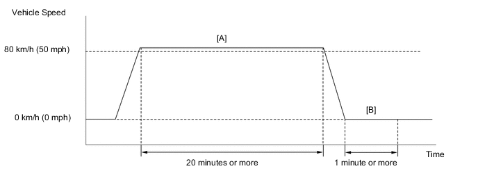
Perform the following the confirmation driving pattern.
CAUTION:
When performing the confirmation driving pattern, obey all speed limits and traffic laws.
-
Drive the vehicle at 80 km/h (50 mph) or more for 20 minutes or more [A].
-
Stop the vehicle.
-
Idle the engine for 1 minute or more [B].
-
Enter the following menus: Powertrain / Engine / Trouble Codes.
-
Read pending DTCs.
Tech Tips
-
If a pending DTC is output, the system is malfunctioning.
-
If a pending DTC is not output, perform the following procedure.
-
-
Enter the following menus: Powertrain / Engine / Utility / All Readiness.
-
Input the DTC: P0420.
-
Check the DTC judgment result.
GTS Display Description NORMAL
-
DTC judgment completed
-
System normal
ABNORMAL
-
DTC judgment completed
-
System abnormal
INCOMPLETE
-
DTC judgment not completed
-
Perform driving pattern after confirming DTC enabling conditions
N/A
-
Unable to perform DTC judgment
-
Number of DTCs which do not fulfill DTC preconditions has reached ECU memory limit
Tech Tips
-
If the judgment result shows NORMAL, the system is normal.
-
If the judgment result shows ABNORMAL, the system has a malfunction.
-
-
If the test result is INCOMPLETE or N/A and no DTC is output, perform a universal trip and check for permanent DTCs Click here.
Tech Tips
-
If a permanent DTC is output, the system is malfunctioning.
-
If no permanent DTC is output, the system is normal.
-
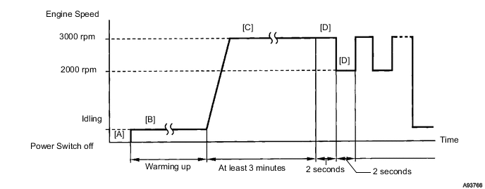
CONDITIONING FOR SENSOR TESTING
-
Connect the GTS to the DLC3 [A].
-
Start the engine and warm it up with all the accessories switched off, until the engine coolant temperature stabilizes [B].
-
Run the engine at an engine speed of between 2500 rpm and 3000 rpm for at least 3 minutes [C].
-
While running the engine at 3000 rpm and 2000 rpm for 2 seconds, check the waveforms of the air fuel ratio and heated oxygen sensors using the GTS [D].
Tech Tips
-
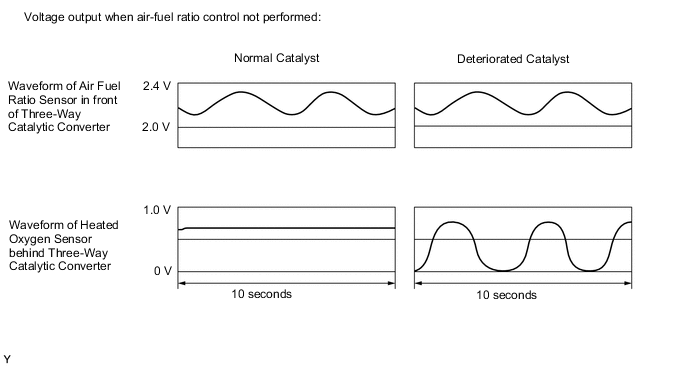
If either of the voltage outputs of either the air fuel ratio or heated oxygen sensor does not fluctuate, or either of the sensors makes a noise, the sensor may be malfunctioning.
-
If the voltage outputs of both the sensors remain lean or rich, the air fuel ratio may be extremely lean or rich. In such cases, enter the following menus: Powertrain / Engine / Active Test / Control the Injection Volume for A/F Sensor.
-
If the three-way catalytic converter has deteriorated, the heated oxygen sensor (located behind the three-way catalytic converter) voltage output fluctuates up and down frequently, even under normal driving conditions.
CAUTION / NOTICE / HINT
Tech Tips
-
If a malfunction cannot be found when troubleshooting DTC P0420, a lean or rich abnormality may be the cause. Perform troubleshooting by following the inspection procedure for P0171 (System Too Lean) and P0172 (System Too Rich).
-
Bank 1 refers to the bank that includes the No. 1 cylinder*.
*: The No. 1 cylinder is the cylinder which is farthest from transmission.
-
Bank 2 refers to the bank that does not include the No. 1 cylinder.
-
Sensor 1 refers to the sensor closest to the engine assembly.
-
Sensor 2 refers to the sensor farthest away from the engine assembly.
-
Read freeze frame data using the GTS. The ECM records vehicle and driving condition information as freeze frame data the moment a DTC is stored. When troubleshooting, freeze frame data can help determine if the vehicle was moving or stationary, if the engine was warmed up or not, if the air fuel ratio was lean or rich, and other data from the time the malfunction occurred.
PROCEDURE
-
CHECK ANY OTHER DTCS OUTPUT
-
Connect the GTS to the DLC3.
-
Turn the ignition switch to ON.
-
Turn the GTS on.
-
Enter the following menus: Powertrain / Engine / Trouble Codes.
-
Read the DTCs.
Result Result Proceed to DTC P0420 is output A DTC P0420 and other DTCs are output B Tech Tips
If any DTCs other than P0420 are output, troubleshoot those DTCs first.
B 
GO TO DTC CHART Click here
A 
-
-
PERFORM ACTIVE TEST USING GTS (Control the Injection Volume)
-
Connect the GTS to the DLC3.
-
Start the engine and warm it up.
-
Turn the GTS on.
-
Run the engine at an engine speed of 2500 rpm for approximately 90 seconds.
-
Enter the following menus: Powertrain / Engine / Active Test / Control the Injection Volume
-
Perform the Active Test operation with the engine idling (press the RIGHT or LEFT button to change the fuel injection volume).
-
Monitor the voltage outputs of the air fuel ratio sensor and heated oxygen sensor (AFS Voltage B1S1 and O2S B1S2) displayed on the GTS.
Tech Tips
-
Change the fuel injection volume within the range of - 12.5% to +12.5%.
-
Each sensor reacts in accordance with increases and decreases in the fuel injection volume.
-
The air fuel ratio sensor has an output delay of a few seconds and the heated oxygen sensor has a maximum output delay of approximately 20 seconds.
-
If the sensor output voltage does not change (almost no reaction) while performing the Active Test, the sensor may be malfunctioning.
Standard GTS Display
(Sensor)
Injection Volume Status Voltage AFS Voltage B1S1
(Air fuel ratio)
+12.5% Rich Below 2.0 V -12.5% Lean Higher than 2.4 V O2S B1S2
(Heated oxygen)
+12.5% Rich Higher than 0.55 V -12.5% Lean Below 0.4 V Result Status
AFS Voltage B1S1
Status
O2S B1S2
A/F Condition and A/F and
HO2 Sensor Conditions
Misfire Main Suspected Trouble Areas Proceed to Lean/Rich Lean/Rich Normal -
-
Three-Way Catalytic Converter (TWC)
-
Gas leakage from exhaust system
A Lean Lean/Rich Air fuel ratio sensor malfunction -
-
Air fuel ratio sensor
B Rich Lean/Rich Air fuel ratio sensor malfunction -
-
Air fuel ratio sensor
Lean/Rich Lean Heated oxygen sensor malfunction -
-
Heated oxygen sensor
-
Gas leakage from exhaust system
C Lean/Rich Rich Heated oxygen sensor malfunction -
-
Heated oxygen sensor
-
Gas leakage from exhaust system
Lean Lean Actual air-fuel ratio lean May occur
-
Extremely rich or lean actual air-fuel ratio
-
Gas leakage from exhaust system
D Rich Rich Actual air-fuel ratio lean -
-
Extremely rich or lean actual air-fuel ratio
-
Gas leakage from exhaust system
Lean: During Control the Injection Volume for A/F Sensor, the air fuel ratio sensor output voltage (AFS Voltage B1S1) is consistently higher than 2.4 V, and the heated oxygen sensor output voltage (O2S B1S2) is consistently below 0.4 V.
Rich: During Control the Injection Volume for A/F Sensor, the AFS Voltage B1S1 is consistently below 2.0 V, and the O2S B1S2 is consistently higher than 0.55 V.
Lean/Rich: During Control the Injection Volume for A/F Sensor of the Active Test, the output voltage of the air fuel ratio sensor and heated oxygen sensor alternate correctly.
-
B
REPLACE AIR FUEL RATIO SENSOR Click here
C 
CHECK FOR EXHAUST GAS LEAK Click here
D
CHECK FOR EXHAUST GAS LEAK Click here
A
-
-
CHECK FOR EXHAUST GAS LEAK
-
Check for exhaust gas leaks.
OK No gas leaks.
NG
REPAIR OR REPLACE EXHAUST GAS LEAK POINT
OK
-
-
REPLACE EXHAUST MANIFOLD (TWC: FRONT CATALYST)
-
Replace the exhaust manifold (TWC: front catalyst) Click here.
NEXT
REPLACE FRONT EXHAUST PIPE ASSEMBLY (TWC: REAR CATALYST) Click here
-
-
CHECK FOR EXHAUST GAS LEAK
-
Check for exhaust gas leaks.
OK No gas leaks.
OK
REPLACE HEATED OXYGEN SENSOR Click here
NG
REPAIR OR REPLACE EXHAUST GAS LEAK POINT
-
-
CHECK FOR EXHAUST GAS LEAK
-
Check for exhaust gas leaks.
OK No gas leaks.
OK
CHECK CAUSE OF EXTREMELY RICH OR LEARN ACTUAL AIR FUEL RATIO Click here
NG
REPAIR OR REPLACE EXHAUST GAS LEAK POINT
-