SFI SYSTEM, Diagnostic DTC:P0191, P0192, P0193
| DTC Code | DTC Name |
|---|---|
| P0191 | Fuel Rail Pressure Sensor Circuit Range / Performance |
| P0192 | Fuel Rail Pressure Sensor Circuit Low Input |
| P0193 | Fuel Rail Pressure Sensor Circuit High Input |
DESCRIPTION
The fuel pressure sensor is installed on the delivery pipe. The sensor changes fuel pressure to an electrical signal and sends the signal to the ECM. Then the ECM controls the pump discharge using this feedback to maintain the fuel's target pressure. If the sensor output stops, the ECM will stop the high pressure side fuel pump and supply fuel using the low pressure side fuel pump.
| DTC No. | DTC Detection Condition | Trouble Area |
|---|---|---|
| P0191 | One of the following conditions is met (2 trip detection logic):
|
|
| P0192 | Fuel pressure sensor voltage is too low for 2.5 seconds or more. (1 trip detection logic) |
|
| P0193 | Fuel pressure sensor voltage is too high for 2.5 seconds or more. (1 trip detection logic) |
|
Tech Tips
After confirming DTC P0192 or P0193, use the GTS to confirm the fuel pressure in the delivery pipe by entering the following menus: Powertrain / Engine / Data List / Fuel Press.
| Fuel Pressure (kPa) | Malfunction |
|---|---|
| Approximately 0 |
|
| Approximately 26000 |
|
MONITOR DESCRIPTION
These DTCs are set if the fuel pressure sensor output voltage is out of the standard range. The DTCs stand for an open or short malfunction of the sensor circuit.
If these DTCs are set, the ECM enters fail-safe mode and limits the engine power. Fail-safe mode continues until the ignition switch is turned off.
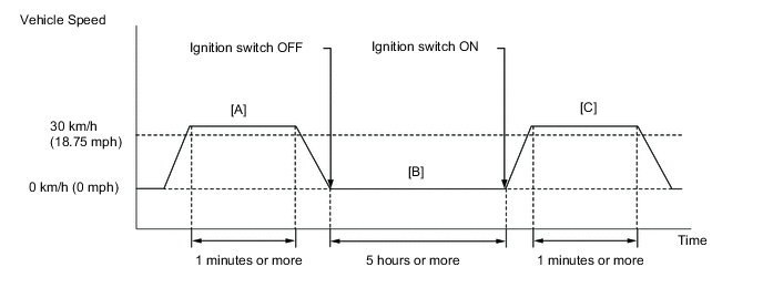
CONFIRMATION DRIVING PATTERN
- P0191
-
-
Connect the GTS to the DLC3.
-
Turn the ignition switch to ON and turn the GTS on.
-
Clear DTCs (even if no DTCs are stored, perform the clear DTC operation) Click here.
-
Turn the ignition switch off and wait for at least 30 seconds.
-
Turn the ignition switch to ON.
-
Start the engine and warm it up until the engine coolant temperature reaches 75°C (167°F) or higher.
-
With the vehicle stationary, depress the accelerator pedal and maintain an engine speed of between 2500 and 3000 rpm for 40 seconds or more.
-
Drive the vehicle at 30 km/h (18.75 mph) or more for 1 minute or more [A].
CAUTION:
When performing the confirmation driving pattern, obey all speed limits and traffic laws.
-
Turn the ignition switch off and leave vehicle for 5 hours or more [B].
-
Turn the ignition switch to ON and turn the GTS on.
-
Enter the following menus: Powertrain / Engine / Trouble Codes.
-
Start the engine and warm it up until the engine coolant temperature reaches 75°C (167°F) or higher.
-
Drive the vehicle at 30 km/h (18.75 mph) or more for 1 minute or more [C].
CAUTION:
When performing the confirmation driving pattern, obey all speed limits and traffic laws.
-
Read pending DTCs.
Tech Tips
-
If a pending DTC is output, the system is malfunctioning.
-
If a pending DTC is not output, perform the following procedure.
-
-
Enter the following menus: Powertrain / Engine / Utility / All Readiness.
-
Input the DTC: P0191.
-
Check the DTC judgment result.
GTS Display Description NORMAL
-
DTC judgment completed
-
System normal
ABNORMAL
-
DTC judgment completed
-
System abnormal
INCOMPLETE
-
DTC judgment not completed
-
Perform driving pattern after confirming DTC enabling conditions
N/A
-
Unable to perform DTC judgment
-
Number of DTCs which do not fulfill DTC preconditions has reached ECU memory limit
Tech Tips
-
If the judgment result shows NORMAL, the system is normal.
-
If the judgment result shows ABNORMAL, the system has a malfunction.
-
-
If the test result is INCOMPLETE or N/A and no DTC is output, perform a universal trip and check for permanent DTCs Click here.
Tech Tips
-
If a permanent DTC is output, the system is malfunctioning.
-
If no permanent DTC is output, the system is normal.
-
-
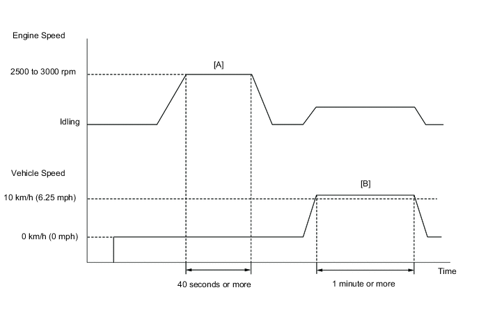
- P0192, P0193
-
-
Connect the GTS to the DLC3.
-
Turn the ignition switch to ON and turn the GTS on.
-
Clear DTCs (even if no DTCs are stored, perform the clear DTC operation) Click here.
-
Turn the ignition switch off and wait for at least 30 seconds.
-
Turn the ignition switch to ON and turn the GTS on.
-
Start the engine and warm it up until the engine coolant temperature reaches 75°C (167°F) or higher.
-
With the vehicle stationary, depress the accelerator pedal and maintain an engine speed of between 2500 and 3000 rpm for 40 seconds or more [A].
-
Drive the vehicle at 10 km/h (6.25 mph) or more for 1 minute or more [B].
CAUTION:
When performing the confirmation driving pattern, obey all speed limits and traffic laws.
-
Enter the following menus: Powertrain / Engine / Trouble Codes.
-
Read pending DTCs.
Tech Tips
-
If a pending DTC is output, the system is malfunctioning.
-
If a pending DTC is not output, perform the following procedure.
-
-
Enter the following menus: Powertrain / Engine / Utility / All Readiness.
-
Input the DTC: P0192 or P0193.
-
Check the DTC judgment result.
GTS Display Description NORMAL
-
DTC judgment completed
-
System normal
ABNORMAL
-
DTC judgment completed
-
System abnormal
INCOMPLETE
-
DTC judgment not completed
-
Perform driving pattern after confirming DTC enabling conditions
N/A
-
Unable to perform DTC judgment
-
Number of DTCs which do not fulfill DTC preconditions has reached ECU memory limit
Tech Tips
-
If the judgment result shows NORMAL, the system is normal.
-
If the judgment result shows ABNORMAL, the system has a malfunction.
-
-
If the test result is INCOMPLETE or N/A and no DTC is output, perform a universal trip and check for permanent DTCs Click here.
Tech Tips
-
If a permanent DTC is output, the system is malfunctioning.
-
If no permanent DTC is output, the system is normal.
-
-
WIRING DIAGRAM
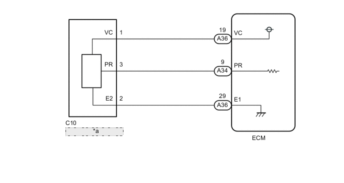
| *a | Fuel Pressure Sensor |
CAUTION / NOTICE / HINT
Tech Tips
Read freeze frame data using the GTS. The ECM records vehicle and driving condition information as freeze frame data the moment a DTC is stored. When troubleshooting, freeze frame data can help determine if the vehicle was moving or stationary, if the engine was warmed up or not, if the air fuel ratio was lean or rich, and other data from the time the malfunction occurred.
PROCEDURE
-
READ VALUE USING GTS (FUEL PRESS)
-
Connect the GTS to the DLC3.
-
Start the engine.
-
Turn the GTS on.
-
Enter the following menus: Powertrain / Engine / Data List / Fuel Press.
-
Read the values.
Result Fuel Pressure (kPa) Proceed to 26000 or more A Approximately 0 3000 to 5000* B Tech Tips
*: The value must change when the engine is moving or stationary.
B 
CHECK FOR INTERMITTENT PROBLEMS Click here
A 
-
-
INSPECT FUEL PRESSURE SENSOR (FUEL PRESSURE SENSOR POWER SOURCE)
-
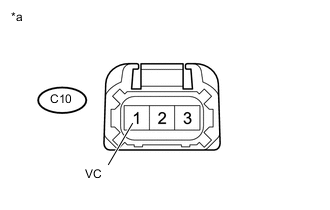
Text in Illustration *a Front view of wire harness connector
(to Fuel Pressure Sensor)
Disconnect the fuel pressure sensor connector.
-
Turn the ignition switch to ON.
-
Measure the voltage according to the value(s) in the table below.
Standard Voltage Tester Connection Switch Condition Specified Condition C10-1 (VC) - Body ground Ignition switch ON 4.5 to 5.5 V
NG 
CHECK HARNESS AND CONNECTOR (ECM - FUEL PRESSURE SENSOR) Click here
OK
-
-
INSPECT ECM (PR VOLTAGE)
-
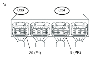
Text in Illustration *a Component with harness connected
(ECM)
Start the engine.
-
Measure the voltage according to the value(s) in the table below.
Standard Voltage Tester Connection Condition Specified Condition A34-9 (PR) - A36-29 (E1) Idling with warm engine 1.0 to 1.7 V Tech Tips
The fuel pressure in the delivery pipe is 3 to 5 MPa.
OK
REPLACE ECM Click here
NG
-
-
CHECK HARNESS AND CONNECTOR (ECM - FUEL PRESSURE SENSOR)
-
Disconnect the ECM connectors.
-
Disconnect the fuel pressure sensor connector.
-
Measure the resistance according to the value(s) in the table below.
Standard Resistance (Check for open) Tester Connection Condition Specified Condition A34-9 (PR) - C10-3 (PR) Always Below 1 Ω A36-29 (E1) - C10-2 (E2) Always Below 1 Ω Standard Resistance (Check for short) Tester Connection Condition Specified Condition A34-9 (PR) or C10-3 (PR) - body ground Always 10 kΩ or higher A34-29 (E1) or C10-2 (E2) - body ground Always 10 kΩ or higher
OK
REPLACE FUEL PRESSURE SENSOR Click here
NG
REPAIR OR REPLACE HARNESS OR CONNECTOR (ECM - FUEL PRESSURE SENSOR)
-
-
CHECK HARNESS AND CONNECTOR (ECM - FUEL PRESSURE SENSOR)
-
Disconnect the fuel pressure sensor connector.
-
Disconnect the ECM connector.
-
Measure the resistance according to the value(s) in the table below.
Standard Resistance (Check for open) Tester Connection Condition Specified Condition A36-19 (VC) - C10-1 (VC) Always Below 1 Ω Standard Resistance (Check for short) Tester Connection Condition Specified Condition A36-19 (VC) or C10-1 (VC) - Body ground Always 10 kΩ or higher
OK
REPLACE ECM Click here
NG
REPAIR OR REPLACE HARNESS OR CONNECTOR (ECM - FUEL PRESSURE SENSOR)
-