SFI SYSTEM, Diagnostic DTC:P0131, P0132, P0134
| DTC Code | DTC Name |
|---|---|
| P0131 | Oxygen Sensor Circuit Low Voltage (Bank 1 Sensor 1) |
| P0132 | Oxygen Sensor Circuit High Voltage Bank1 Sensor1 |
| P0134 | Oxygen Sensor Circuit No Activity Detected (Bank 1 Sensor 1) |
DESCRIPTION
-
Refer to DTC P2195 Click here.
Tech Tips
-
Although the DTC titles say oxygen sensor, these DTCs relate to the air fuel ratio sensor.
-
Sensor 1 refers to the sensor mounted in front of the three-way catalytic converter and located near the engine assembly.
-
| DTC No. | DTC Detection Condition | Trouble Area |
|---|---|---|
| P0131 | One of the following conditions is met for 1 second or more (1 trip detection logic):
|
|
| P0132 | One of the following conditions is met for 1 second or more (1 trip detection logic):
|
|
| P0134 | Air fuel ratio sensor impedance is 450 Ω or more for 5 seconds or more. (1 trip detection logic) |
MONITOR DESCRIPTION
These DTCs are output when there is an open or short in the air fuel ratio sensor circuit, or if the air fuel ratio sensor output drops. To detect these problems, the voltage of the air fuel ratio sensor is monitored when turning the ignition switch to ON, and the admittance (admittance is an electrical term that indicates the ease of flow of current) is checked while driving. If the voltage of the air fuel ratio sensor is between 0.6 V and 4.5 V, it is considered normal. If the voltage is out of the specified range, or the admittance is less than the standard value, the ECM determines that there is a malfunction in the air fuel ratio sensor. If the same malfunction is detected in next driving cycle, the MIL is illuminated and a DTC is stored.
CONFIRMATION DRIVING PATTERN
-
Connect the GTS to the DLC3.
-
Turn the ignition switch to ON and turn the GTS on.
-
Clear DTCs (even if no DTCs are stored, perform the clear DTC operation) Click here.
-
Turn the ignition switch off and wait for at least 30 seconds.
-
Turn the ignition switch to ON and turn the GTS on.
-
Start the engine and warm it up until the engine coolant temperature reaches 75°C (167°F) or higher.
-
Perform the following the confirmation driving pattern.
CAUTION:
When performing the confirmation driving pattern, obey all speed limits and traffic laws.
-
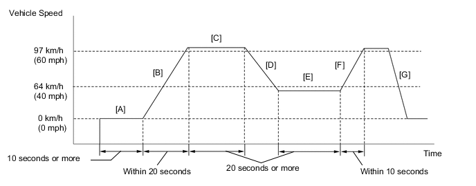
Idle the engine for 10 seconds or more [A].
-
Accelerate the vehicle to 97 km/h (60 mph) or more within 20 seconds [B].
-
Drive the vehicle at 97 km/h (60 mph) or more for 20 seconds or more [C].
-
Release the accelerator pedal to Decelerate until the vehicle speed decreases to less than 64 km/h (40 mph) [D].
Tech Tips
Release the accelerator pedal fully to perform the fuel-cut.
-
Drive the vehicle at 60 km/h (40 mph) or less for 20 seconds or more [E].
-
Accelerate the vehicle to 97 km/h (60 mph) or more within 10 seconds [F].
-
Release the accelerator pedal and stop the vehicle [G].
-
Enter the following menus: Powertrain / Engine / Trouble Codes.
-
Read pending DTCs.
Tech Tips
-
If a pending DTC is output, the system is malfunctioning.
-
If a pending DTC is not output, perform the following procedure.
-
-
Enter the following menus: Powertrain / Engine / Utility / All Readiness.
-
Input the DTC: P0131, P0132 or P0134.
-
Check the DTC judgment result.
GTS Display Description NORMAL
-
DTC judgment completed
-
System normal
ABNORMAL
-
DTC judgment completed
-
System abnormal
INCOMPLETE
-
DTC judgment not completed
-
Perform driving pattern after confirming DTC enabling conditions
N/A
-
Unable to perform DTC judgment
-
Number of DTCs which do not fulfill DTC preconditions has reached ECU memory limit
Tech Tips
-
If the judgment result shows NORMAL, the system is normal.
-
If the judgment result shows ABNORMAL, the system has a malfunction.
-
-
If the test result is INCOMPLETE or N/A and no DTC is output, perform a universal trip and check for permanent DTCs Click here.
Tech Tips
-
If a permanent DTC is output, the system is malfunctioning.
-
If no permanent DTC is output, the system is normal.
-
WIRING DIAGRAM
Refer to DTC P0030 Click here.
CAUTION / NOTICE / HINT
Tech Tips
-
Sensor 1 refers to the sensor closest to the engine assembly.
-
Sensor 2 refers to the sensor farthest away from the engine assembly.
-
Read freeze frame data using the GTS. The ECM records vehicle and driving condition information as freeze frame data the moment a DTC is stored. When troubleshooting, freeze frame data can help determine if the vehicle was moving or stationary, if the engine was warmed up or not, if the air fuel ratio was lean or rich, and other data from the time the malfunction occurred.
-
Refer to "Data List / Active Test" [AFS Voltage B1S1] Click here.
Note
Inspect the fuses for circuits related to this system before performing the following inspection procedure.
PROCEDURE
-
CHECK HARNESS AND CONNECTOR (AIR FUEL RATIO SENSOR - ECM)
-
Disconnect the air fuel ratio sensor connector.
-
Disconnect the ECM connector.
-
Measure the resistance according to the value(s) in the table below.
Standard Resistance (Check for open) Tester Connection Condition Specified Condition A34-19 (A1A+) - C14-3 (A1A+) Always Below 1 Ω A34-18 (A1A-) - C14-4 (A1A-) Always Below 1 Ω A34-5 (HA1A) - C14-1 (HA1A) Always Below 1 Ω Standard Resistance (Check for short) Tester Connection Condition Specified Condition A34-19 (A1A+) or C14-3 (A1A+) - Body ground Always 10 kΩ or higher A34-18 (A1A-) or C14-4 (A1A-) - Body ground Always 10 kΩ or higher A34-5 (HA1A) or C14-1 (HA1A) - Body ground Always 10 kΩ or higher
NG 
REPAIR OR REPLACE HARNESS OR CONNECTOR
OK 
-
-
REPLACE AIR FUEL RATIO SENSOR
-
Replace the air fuel ratio sensor Click here.
NEXT
-
-
CHECK WHETHER DTC OUTPUT RECURS (DTC P0131, P0132 OR P0134)
-
Connect the GTS to the DLC3.
-
Turn the ignition switch to ON.
-
Turn the GTS on.
-
Clear the DTCs Click here.
-
Turn the ignition switch off and wait for at least 30 seconds.
-
Turn the ignition switch to ON.
-
Turn the GTS on.
-
Drive the vehicle in accordance with the driving pattern described in the Confirmation Driving Pattern.
-
Enter the following menus: Powertrain / Engine / Utility / All Readiness.
-
Input the DTC: P0131, P0132 or P0134.
-
Check the DTC judgment.
Result Result Proceed to NORMAL (DTC is not output) A ABNORMAL (DTC P0131, P0132 or P0134 is output) B
A
END
B
REPLACE ECM Click here
-