SFI SYSTEM, Diagnostic DTC:P0117, P0118
| DTC Code | DTC Name |
|---|---|
| P0117 | Engine Coolant Temperature Circuit Low Input |
| P0118 | Engine Coolant Temperature Circuit High Input |
DESCRIPTION
A thermistor, whose resistance value varies according to the engine coolant temperature, is built into the engine coolant temperature sensor. The structure of the sensor and its connection to the ECM are the same as those of the intake air temperature sensor.
Tech Tips
When any of DTCs P0117 and P0118 is stored, the ECM enters fail-safe mode. During fail-safe mode, the engine coolant temperature is estimated to be 70°C (158°F) by the ECM. Fail-safe mode continues until a pass condition is detected.
| DTC No. | DTC Detection Condition | Trouble Area |
|---|---|---|
| P0117 | Engine coolant temperature sensor voltage is less than 0.47 V for 0.5 seconds or more. (1 trip detection logic) |
|
| P0118 | Engine coolant temperature sensor voltage is more than 4.698 V for 0.5 seconds or more. (1 trip detection logic) |
|
Tech Tips
When any of these DTCs are output, check the engine coolant temperature using the GTS. Enter the following menus: Powertrain / Engine / Data List / Coolant Temp.
| Temperature Displayed | Malfunction |
|---|---|
| -40°C (-40°F) | Open circuit |
| 120°C (248°F) | Short circuit |
MONITOR DESCRIPTION
The engine coolant temperature sensor is used to monitor the engine coolant temperature. The engine coolant temperature sensor has a thermistor with a resistance that varies according to the temperature of the engine coolant. When the coolant temperature is low, the resistance in the thermistor increases. When the temperature is high, the resistance drops. These variations in resistance are reflected in the output voltage from the sensor. The ECM monitors the sensor voltage and uses this value to calculate the engine coolant temperature. When the sensor output voltage deviates from the normal operating range, the ECM interprets this as a fault in the engine coolant temperature sensor circuit and stores a DTC.
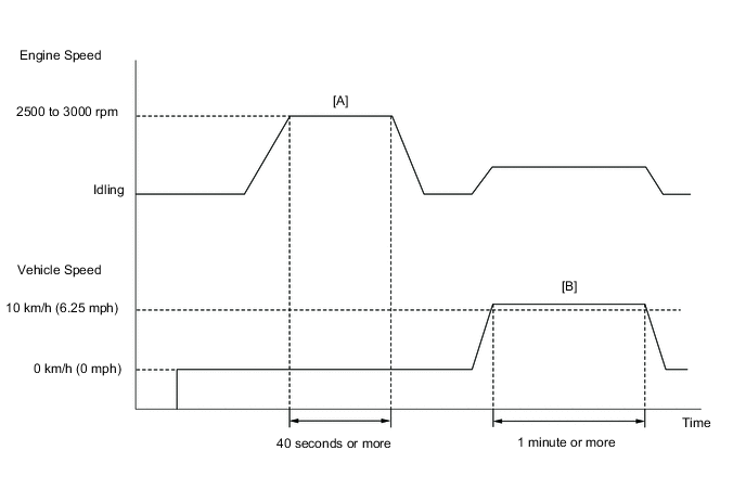
CONFIRMATION DRIVING PATTERN
-
-
Connect the GTS to the DLC3.
-
Turn the ignition switch to ON and turn the GTS on.
-
Clear DTCs (even if no DTCs are stored, perform the clear DTC operation) Click here.
-
Turn the ignition switch off and wait for at least 30 seconds.
-
Turn the ignition switch to ON and turn the GTS on.
-
Start the engine and warm it up until the engine coolant temperature reaches 75°C (167°F) or higher.
-
With the vehicle stationary, depress the accelerator pedal and maintain an engine speed of between 2500 and 3000 rpm for 40 seconds or more [A].
-
Drive the vehicle at 10 km/h (6.25 mph) or more for 1 minute or more [B].
CAUTION:
When performing the confirmation driving pattern, obey all speed limits and traffic laws.
-
Enter the following menus: Powertrain / Engine / Trouble Codes.
-
Read pending DTCs.
Tech Tips
-
If a pending DTC is output, the system is malfunctioning.
-
If a pending DTC is not output, perform the following procedure.
-
-
Enter the following menus: Powertrain / Engine / Utility / All Readiness.
-
Input the DTC: P0117 or P0118.
-
Check the DTC judgment result.
GTS Display Description NORMAL
-
DTC judgment completed
-
System normal
ABNORMAL
-
DTC judgment completed
-
System abnormal
INCOMPLETE
-
DTC judgment not completed
-
Perform driving pattern after confirming DTC enabling conditions
N/A
-
Unable to perform DTC judgment
-
Number of DTCs which do not fulfill DTC preconditions has reached ECU memory limit
Tech Tips
-
If the judgment result shows NORMAL, the system is normal.
-
If the judgment result shows ABNORMAL, the system has a malfunction.
-
-
If the test result is INCOMPLETE or N/A and no DTC is output, perform a universal trip and check for permanent DTCs Click here.
Tech Tips
-
If a permanent DTC is output, the system is malfunctioning.
-
If no permanent DTC is output, the system is normal.
-
WIRING DIAGRAM
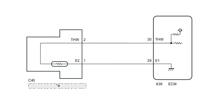
| *a | Engine Coolant Temperature Sensor |
CAUTION / NOTICE / HINT
Tech Tips
-
Read freeze frame data using the GTS. The ECM records vehicle and driving condition information as freeze frame data the moment a DTC is stored. When troubleshooting, freeze frame data can help determine if the vehicle was moving or stationary, if the engine was warmed up or not, if the air fuel ratio was lean or rich, and other data from the time the malfunction occurred.
-
If DTC P0117 is stored, check that the engine does not overheat (the DTC P0117 may be stored due to engine overheating).
PROCEDURE
-
READ VALUE USING GTS (ENGINE COOLANT TEMPERATURE)
-
Connect the GTS to the DLC3.
-
Turn the ignition switch to ON.
-
Turn the GTS on.
-
Enter the following menus: Powertrain / Engine / Data List / Coolant Temp.
-
Read the value displayed on the GTS.
Standard value Between 75 and 100°C (167 and 212°F) with warm engine. Result Result Proceed to -40°C (-40°F) A 120°C (248°F) B Between 75 and 100°C (167 and 212°F) C Tech Tips
-
If there is an open circuit, the GTS indicates -40°C (-40°F).
-
If there is a short circuit, the GTS indicates higher than 215°C (419°F).
-
B 
READ VALUE USING GTS (CHECK FOR SHORT IN WIRE HARNESS) Click here
C 
CHECK FOR INTERMITTENT PROBLEMS Click here
A 
-
-
READ VALUE USING GTS (CHECK FOR OPEN IN WIRE HARNESS)
-
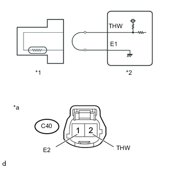
Text in Illustration *1 Engine Coolant Temperature Sensor *2 ECM *a Front view of wire harness connector
(to Engine Coolant Temperature Sensor)
Disconnect the engine coolant temperature sensor connector.
-
Connect terminals 1 and 2 of the engine coolant temperature sensor connector on the wire harness side.
-
Connect the GTS to the DLC3.
-
Turn the ignition switch to ON.
-
Turn the GTS on.
-
Enter the following menus: Powertrain / Engine / Data List / Coolant Temp.
-
Read the value displayed on the GTS.
Standard value Higher than 120°C (248°F)
OK
REPLACE ENGINE COOLANT TEMPERATURE SENSOR Click here
NG
-
-
CHECK HARNESS AND CONNECTOR (ENGINE COOLANT TEMPERATURE SENSOR - ECM)
-
Disconnect the engine coolant temperature sensor connector.
-
Disconnect the ECM connector.
-
Measure the resistance according to the value(s) in the table below.
Standard Resistance (Check for open) Tester Connection Condition Specified Condition A36-30 (THW) - C40-2 (THW) Always Below 1 Ω A36-29 (E1) - C40-1 (E2) Always Below 1 Ω
OK
REPLACE ECM Click here
NG
REPAIR OR REPLACE HARNESS OR CONNECTOR
-
-
READ VALUE USING GTS (CHECK FOR SHORT IN WIRE HARNESS)
-
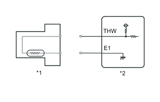
Text in Illustration *1 Engine Coolant Temperature Sensor *2 ECM Disconnect the engine coolant temperature sensor connector.
-
Connect the GTS to the DLC3.
-
Turn the ignition switch to ON.
-
Turn the GTS on.
-
Enter the following menus: Powertrain / Engine / Data List / Coolant Temp.
-
Read the value displayed on the GTS.
Standard value -40°C (-40°F)
OK
REPLACE ENGINE COOLANT TEMPERATURE SENSOR Click here
NG
-
-
CHECK HARNESS AND CONNECTOR (ENGINE COOLANT TEMPERATURE SENSOR - ECM)
-
Disconnect the engine coolant temperature sensor connector.
-
Disconnect the ECM connector.
-
Measure the resistance according to the value(s) in the table below.
Standard Resistance (Check for short) Tester Connection Condition Specified Condition A36-30 (THW) or C40-2 (THW) - Body ground Always 10 kΩ or higher A36-29 (E1) or C40-1 (E2) - Body ground Always 10 kΩ or higher
OK
REPLACE ECM Click here
NG
REPAIR OR REPLACE HARNESS OR CONNECTOR
-