AUTOMATIC TRANSMISSION ASSEMBLY REMOVAL

PROCEDURE
-
DISCONNECT CABLE FROM NEGATIVE BATTERY TERMINAL
-
REMOVE NO. 1 ENGINE UNDER COVER
-
REMOVE NO. 2 ENGINE UNDER COVER
-
REMOVE REAR ENGINE UNDER COVER LH (w/ Floor Under Cover)
-
REMOVE REAR ENGINE UNDER COVER RH (w/ Floor Under Cover)
Tech Tips
Use the same procedure for the RH side as for the LH side.
-
DRAIN AUTOMATIC TRANSMISSION FLUID
-
REMOVE PROPELLER WITH CENTER BEARING SHAFT ASSEMBLY
-
REMOVE FRONT STABILIZER BAR
-
REMOVE STARTER ASSEMBLY
-
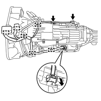
DISCONNECT WIRING HARNESS CONNECTOR
Tech Tips
Fix disconnected harness components with tape to keep them out of the way.
-
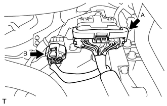
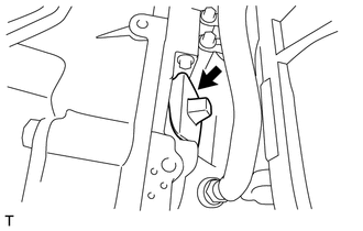
Release the lock of connector (A) and disconnect the connector.
-
Disconnect the connector (B).
-
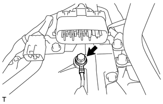
Remove the bolt and disconnect the ground cable.
-
Disengage the 4 wire harness clamps.
-
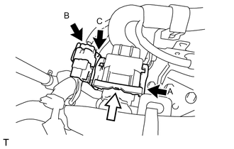
Release the lock of connector (A) and disconnect the connector.
-
Disconnect the connector (B) and (C).
-
Disengage the wire harness clamp.
-
Remove the bolt and the wire harness clamp bracket.
-
Remove the 2 bolts and the No. 2 engine hanger.
-
-
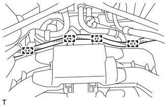
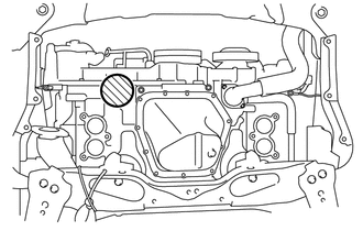
DISCONNECT VACUUM TUBE CONNECTOR HOSE (for LHD)
-
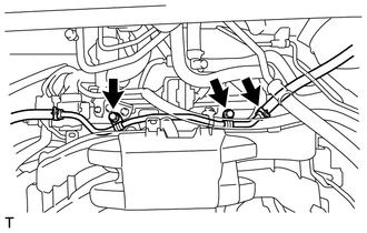
Remove the 2 bolts and the disconnect the union to check valve hose.
-
-
REMOVE FLYWHEEL HOUSING UNDER COVER
-
Remove the flywheel housing side cover from the automatic transmission assembly.
-
-
REMOVE DRIVE PLATE AND TORQUE CONVERTER SETTING BOLT
-
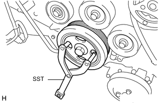
Using SST, hold the crankshaft pulley.
- SST
- 09960-10010 ( 09962-01000, 09963-01000 )
-

Remove the 6 drive plate and torque converter setting bolt.
-
-
DISCONNECT AUTOMATIC TRANSMISSION ASSEMBLY
-
Remove the 2 bolts from the automatic transmission assembly.
-
-
REMOVE EXHAUST MANIFOLD
-
SUSPEND ENGINE ASSEMBLY
-
Support the engine assembly with an engine lifter so that it is stable shown in the illustration.
Text in Illustration 
Attachment Placement Positions Note
-
Set the engine assembly with transmission so that it is horizontal.
-
Never attach the attachment and plate lift attachment to the oil pan section of the engine assembly.
-
-
-
REMOVE TRANSMISSION OIL COOLER HOSE
-
Loosen the 4 hose clamps and remove the 2 transmission oil cooler hoses.
Note
Use a container to catch any coolant which flows out of the transmission oil cooler hoses.
-
-
SEPARATE OIL COOLER TUBE
-
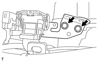
Remove the 2 bolts and separate the oil cooler tube.
-
-
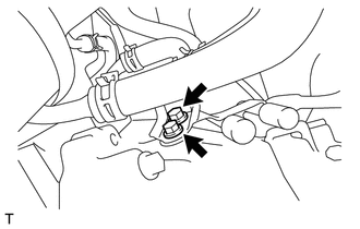
REMOVE TRANSMISSION REVOLUTION SENSOR (NT)
-
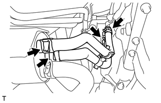
REMOVE FLOOR SHIFT GEAR SHIFTING ROD SUB-ASSEMBLY
-
While pushing the shift lock release button, move the shift lever to N.
-
Remove the clip, pin and the floor shift gear shifting rod sub-assembly from the transmission control shaft lever RH.
-
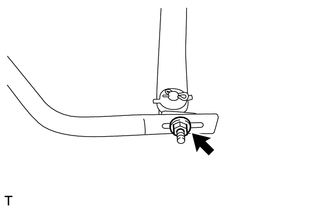
Remove the nut and disconnect the floor shift gear shifting rod sub-assembly.
-
-
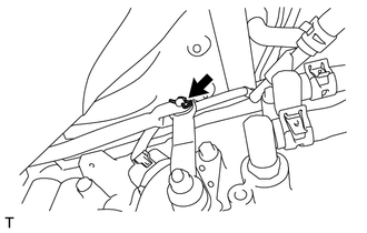
REMOVE EXHAUST PIPE BRACKET
-
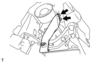
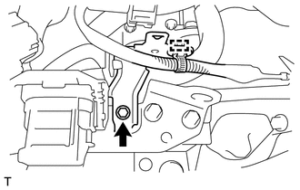
Remove the 2 bolts and the exhaust pipe bracket from the automatic transmission assembly.
-
-
SUPPORT AUTOMATIC TRANSMISSION ASSEMBLY
-
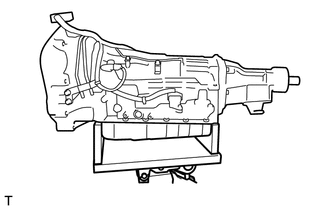
Support the automatic transmission assembly with a high transmission jack.
Note
To prevent damage to and deformation of the oil pan, never place a jack under the oil pan area of the automatic transmission assembly.
-
-
REMOVE REAR NO. 2 ENGINE MOUNTING INSULATOR
-
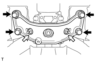
Remove the 4 bolts, 2 washers and 2 nuts and the rear No. 2 engine mounting insulator from the rear No. 1 engine mounting insulator.
Text in Illustration 
Bolt 
Nut
-
-
REMOVE REAR NO. 1 ENGINE MOUNTING INSULATOR
-
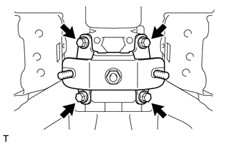
Remove the 4 bolts and the rear No. 1 engine mounting insulator from the automatic transmission assembly.
-
-
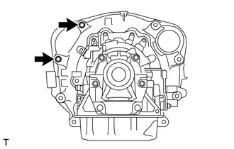
REMOVE AUTOMATIC TRANSMISSION ASSEMBLY
-
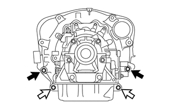
Remove the 2 bolts and 2 nuts and the automatic transmission assembly from the engine assembly.
Text in Illustration Bolt Nut Note
-
To prevent damage to the knock pins, do not pry between the automatic transmission assembly and the engine assembly.
-
Do not allow the torque converter to fall off.
-
-
-
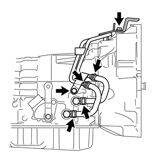
DISCONNECT WIRE HARNESS
-
Disconnect the park/neutral position switch connector, transmission wire connector and the transmission revolution sensor connector.
Tech Tips
Disengage the claw, press down the lever, and disconnect the transmission wire connector.
-
Disengage the 6 wire harness clamps and the wire harness from the automatic transmission assembly.
-
-
REMOVE OIL COOLER TUBE
-
Loosen the 4 hose clamps and remove the 2 oil cooler hoses.
Note
Use a container to catch any coolant which flows out of the oil cooler hoses.
-
Remove the 2 bolts and the oil cooler tube from the automatic transmission assembly.
-
-
REMOVE TORQUE CONVERTER ASSEMBLY
-
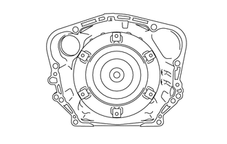
Remove the torque converter assembly from the automatic transmission assembly.
Note
Remove the torque converter assembly from the input shaft horizontally.
-
-
INSPECT TORQUE CONVERTER ASSEMBLY