SHIFT LEVER INSPECTION
PROCEDURE
-
INSPECT TRANSMISSION CONTROL SWITCH (SHIFT LEVER ASSEMBLY)
-
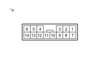
Text in Illustration *a Component without harness connected
(Transmission Control Switch (Shift Lever Assembly))
Measure the resistance according to the value(s) in the table below.
Standard Resistance Tester Connection Condition Specified Condition 1 - 3 Shift lever not in P Below 1 Ω 2 - 3 Shift lever in P 8 - 9 Shift lever in M
Shift lever held in "+"
(Up shift)
10 - 11 Shift lever in M 12 - 13 Shift lever in M
Shift lever held in "-"
(Down shift)
1 - 3 Shift lever in P 10 kΩ or higher 2 - 3 Shift lever not in P 8 - 9 Shift lever in M
Shift lever not in "+"
10 - 11 Shift lever not in M 12 - 13 Shift lever in M
Shift lever not in "-"
If the result is not as specified, replace the transmission control switch.
-
-
INSPECT SHIFT LOCK CONTROL UNIT ASSEMBLY (SHIFT LEVER ASSEMBLY)
-
Text in Illustration *a Component without harness connected
(Shift Lock Control Unit Assembly)
Measure the resistance according to the value(s) in the table below.
Standard Resistance Tester Connection Condition Specified Condition 4 - 5 20°C (68°F) 27.6 to 30.5 Ω If the result is not as specified, replace the shift lock control unit assembly.
-