VALVE BODY ASSEMBLY INSPECTION
PROCEDURE
-
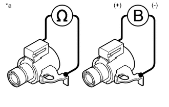
INSPECT SHIFT SOLENOID VALVE SL1 AND SL2
-
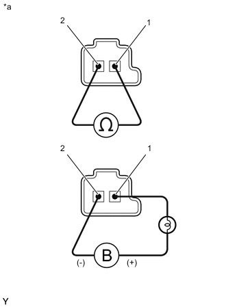
Text in Illustration *a Component without harness connected
(Shift Solenoid Valve SL1 and SL2)
Measure the resistance according to the value(s) in the table below.
Standard Resistance Tester Connection Condition Specified Condition 1 - 2 20°C (68°F) 5.0 to 5.6 Ω -
Connect the positive (+) lead with a 21 W bulb to terminal 1 and the negative (-) lead to terminal 2 of the shift solenoid valve connector, then check the movement of the valve.
OK The solenoid makes an operating sound. If the result is not as specified, replace the shift solenoid valve.
-
-
INSPECT SHIFT SOLENOID VALVE S1
-
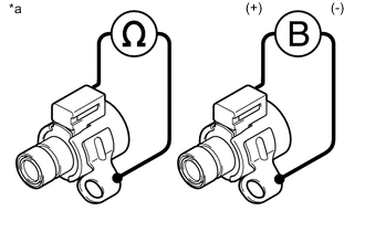
Text in Illustration *a Component without harness connected
(Shift Solenoid Valve S1)
Measure the resistance according to the value(s) in the table below.
Standard Resistance Tester Connection Condition Specified Condition Shift solenoid valve S1 connector terminal - Shift solenoid valve S1 body 20°C (68°F) 11 to 15 Ω -
Connect the positive (+) lead to the terminal of the shift solenoid valve S1 connector, and the negative (-) lead to the shift solenoid valve S1 body.
OK The solenoid makes an operating sound. If the result is not as specified, replace the shift solenoid valve S1.
-
-
INSPECT SHIFT SOLENOID VALVE S2
-
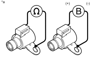
Text in Illustration *a Component without harness connected
(Shift Solenoid Valve S2)
Measure the resistance according to the value(s) in the table below.
Standard Resistance Tester Connection Condition Specified Condition Shift solenoid valve S2 connector terminal - Shift solenoid valve S2 body 20°C (68°F) 11 to 15 Ω -
Connect the positive (+) lead to the terminal of the shift solenoid valve S2 connector, and the negative (-) lead to the shift solenoid valve S2 body.
OK The solenoid makes an operating sound. If the result is not as specified, replace the shift solenoid valve S2.
-
-
INSPECT SHIFT SOLENOID VALVE S3
-
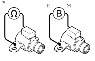
Text in Illustration *a Component without harness connected
(Shift Solenoid Valve S3)
Measure the resistance according to the value(s) in the table below.
Standard Resistance Tester Connection Condition Specified Condition Shift solenoid valve S3 connector terminal - Shift solenoid valve S3 body 20°C (68°F) 11 to 15 Ω -
Connect the positive (+) lead to the terminal of the shift solenoid valve S3 connector, and the negative (-) lead to the shift solenoid valve S3 body.
OK The solenoid makes an operating sound. If the result is not as specified, replace the shift solenoid valve S3.
-
-
INSPECT SHIFT SOLENOID VALVE S4
-
Text in Illustration *a Component without harness connected
(Shift Solenoid Valve S4)
Measure the resistance according to the value(s) in the table below.
Standard Resistance Tester Connection Condition Specified Condition Shift solenoid valve S4 connector terminal - Shift solenoid valve S4 body 20°C (68°F) 11 to 15 Ω -
Connect the positive (+) lead to the terminal of the shift solenoid valve S4 connector, and the negative (-) lead to the shift solenoid valve S4 body.
OK The solenoid makes an operating sound. If the result is not as specified, replace the shift solenoid valve S4.
-
-
INSPECT SHIFT SOLENOID VALVE SR
-
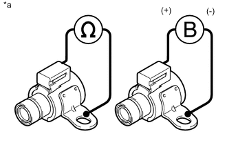
Text in Illustration *a Component without harness connected
(Shift Solenoid Valve SR)
Measure the resistance according to the value(s) in the table below.
Standard Resistance Tester Connection Condition Specified Condition Shift solenoid valve SR connector terminal - Shift solenoid valve SR body 20°C (68°F) 11 to 15 Ω -
Connect the positive (+) lead to the terminal of the shift solenoid valve SR connector, and the negative (-) lead to the shift solenoid valve SR body.
OK The solenoid makes an operating sound. If the result is not as specified, replace the shift solenoid valve SR.
-
-
INSPECT SHIFT SOLENOID VALVE SLT
-

Text in Illustration *a Component without harness connected
(Shift Solenoid Valve SLT)
Measure the resistance according to the value(s) in the table below.
Standard Resistance Tester Connection Condition Specified Condition 1 - 2 20°C (68°F) 5.0 to 5.6 Ω -
Connect the positive (+) lead with a 21 W bulb to terminal 2 and the negative (-) lead to terminal 1 of the shift solenoid valve SLT connector, then check the movement of the valve.
OK The solenoid makes an operating sound. If the result is not as specified, replace the shift solenoid valve SLT.
-
-
INSPECT SHIFT SOLENOID VALVE SLU
-
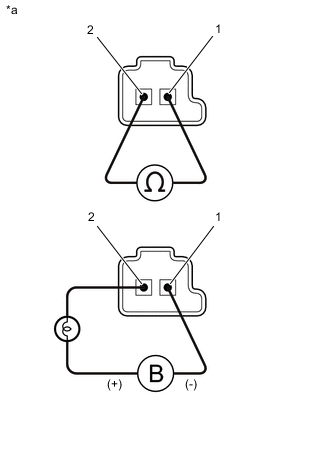
Text in Illustration *a Component without harness connected
(Shift Solenoid Valve SLU)
Measure the resistance according to the value(s) in the table below.
Standard Resistance Tester Connection Condition Specified Condition 1 - 2 20°C (68°F) 5.0 to 5.6 Ω -
Connect the positive (+) lead with a 21 W bulb to terminal 2 and the negative (-) lead to terminal 1 of the shift solenoid valve SLU connector, then check the movement of the valve.
OK The solenoid makes an operating sound. If the result is not as specified, replace the shift solenoid valve SLU.
-