AUTOMATIC TRANSMISSION SYSTEM Pattern Select Switch Circuit
DESCRIPTION
A signal from the pattern select switch assembly input into the TCM enables switching of the mode.
WIRING DIAGRAM
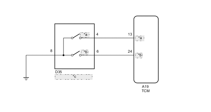
| *a | SPORT |
| *b | SNOW |
| *c | Pattern Select Switch |
Tech Tips
(*) Pattern Select Switch (ECT SNOW Switch)
When the ECT SNOW switch is pushed, the switch contact is made and the ECT SNOW mode is selected.
To cancel the ECT SNOW mode, push the ECT SNOW switch once again.
The ECT SNOW mode is automatically cancelled out when the ignition switch is turned "off".
PROCEDURE
-
READ VALUE USING GTS
-
Connect the GTS to the DLC3.
-
Turn the ignition switch to ON.
-
Read the value displayed on the GTS.
OK Tester Display Measurement Item/Range Normal Condition Diagnostic Note Sport Switch Status Pattern switch (ECT SPORT) status/
ON or OFF
Ignition switch is:
ON: off
↓
Pattern switch (ECT SPORT) is:
Pushed: ON
↓
Pattern switch (ECT SPORT) is:
Pushed: OFF
-
NG 
INSPECT PATTERN SELECT SWITCH ASSEMBLY Click here
OK 
-
-
READ VALUE USING GTS
-
Connect the GTS to the DLC3.
-
Turn the ignition switch to ON.
-
Read the value displayed on the GTS.
OK Tester Display Measurement Item/Range Normal Condition Diagnostic Note Snow Switch Status Pattern switch (ECT SNOW) status/
ON or OFF
Ignition switch is:
ON: off
↓
Pattern switch (ECT SNOW) is:
Pushed: ON
↓
Pattern switch (ECT SNOW) is:
Pushed: OFF
-
OK 
GO TO PROBLEM SYMPTOMS TABLE Click here
NG
INSPECT PATTERN SELECT SWITCH ASSEMBLY Click here
-
-
INSPECT PATTERN SELECT SWITCH ASSEMBLY
-
Perform inspection of the pattern select switch Click here.
NG
REPLACE PATTERN SELECT SWITCH ASSEMBLY Click here
OK
-
-
CHECK HARNESS AND CONNECTOR (PATTERN SELECT SWITCH ASSEMBLY - TCM - BODY GROUND)
-
Disconnect the TCM connector.
-
Disconnect the pattern select switch assembly connector.
-
Measure the resistance according to the value(s) in the table below.
Standard resistance Tester Connection Switch Condition Specified Condition A19-13(SPORT) - D35-4(SPORT) Always Below 1 Ω D35-8 - Body ground Always Below 1 Ω A19-3(SPORT) - Body ground Always 10 kΩ or higher -
Connect the TCM connector.
-
Connect the pattern select switch assembly connector.
NG
REPAIR OR REPLACE HARNESS OR CONNECTOR
OK
-
-
REPLACE TCM
-
Replace the TCM Click here.
NEXT
PERFORM THE RESET MEMORY Click here
-
-
INSPECT PATTERN SELECT SWITCH ASSEMBLY
-
Perform inspection of the pattern select switch Click here.
NG
REPLACE PATTERN SELECT SWITCH ASSEMBLY Click here
OK
-
-
CHECK HARNESS AND CONNECTOR (PATTERN SELECT SWITCH - TCM - BODY GROUND)
-
Disconnect the TCM connector.
-
Disconnect the pattern select switch assembly connector.
-
Measure the resistance according to the value(s) in the table below.
Standard resistance Tester Connection Switch Condition Specified Condition A19-24(SNOW) - D35-6 Always Below 1 Ω D35-8 - Body ground Always Below 1 Ω A19-24(SNOW) - Body ground Always 10 kΩ or higher -
Connect the TCM connector.
-
Connect the pattern select switch assembly connector.
NG
REPAIR OR REPLACE HARNESS OR CONNECTOR
OK
-
-
REPLACE TCM
-
Replace the TCM Click here.
NEXT
PERFORM THE RESET MEMORY Click here
-