AUTOMATIC TRANSMISSION SYSTEM, Diagnostic DTC:B1016

| DTC Code | DTC Name |
|---|---|
| B1016 | Shift Lock Circuit |
DESCRIPTION
When an IGN signal, P switch signal, and STP signal are input into the main body ECU (network gateway ECU), a signal is output to the shift lock control unit assembly.
| DTC No. | DTC Detection Condition
|
Trouble Area |
|---|---|---|
| B1016 |
|
|
WIRING DIAGRAM
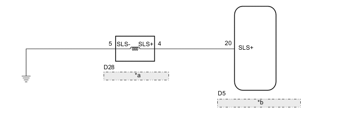
| *a | Shift Lock Control Unit Assembly (Shift Lever Assembly) |
| *b | Main Body ECU(Network Gateway ECU) |
PROCEDURE
-
INSPECT SHIFT LOCK CONTROL UNIT ASSEMBLY
-
Perform inspection of the shift lock control unit assembly Click here.
NG 
REPLACE SHIFT LOCK CONTROL UNIT ASSEMBLY Click here
OK 
-
-
CHECK HARNESS AND CONNECTOR (MAIN BODY ECU - SHIFT LOCK CONTROL UNIT ASSEMBLY)
-
Disconnect the D5 main body ECU (network gateway ECU) connector.
-
Disconnect the D28 shift lock control unit assembly connector.
-
Measure the resistance according to the value(s) in the table below.
Standard Resistance Tester Connection Condition Specified Condition D5-20(SLS+) - D28-4(SLS+) Always Below 1 Ω D5-20(SLS+) or D28-4(SLS+) - Body ground Always 10 kΩ or higher -
Connect the D5 main body ECU (network gateway ECU) connector.
-
Connect the D28 shift lock control unit assembly connector.
NG
REPAIR OR REPLACE HARNESS OR CONNECTOR
OK
-
-
CHECK HARNESS AND CONNECTOR (SHIFT LOCK CONTROL UNIT ASSEMBLY - BODY GROUND)
-
Disconnect the D28 shift lock control unit assembly connector.
-
Measure the resistance according to the value(s) in the table below.
Standard Resistance Tester Connection Condition Specified Condition D28-5(SLS-) - Body ground Always Below 1 Ω -
Connect the D28 shift lock control unit assembly connector.
OK
REPLACE MAIN BODY ECU (NETWORK GATEWAY ECU) Click here
NG
REPAIR OR REPLACE HARNESS OR CONNECTOR (SHIFT LOCK CONTROL UNIT ASSEMBLY - BODY GROUND)
-