AUTOMATIC TRANSMISSION SYSTEM, Diagnostic DTC:P0751, P0752

| DTC Code | DTC Name |
|---|---|
| P0751 | Shift Solenoid "A" Performance (Shift Solenoid Valve S1) |
| P0752 | Shift Solenoid "A" Stuck ON (S1 Solenoid) |
SYSTEM DESCRIPTION
The TCM carries out detection of the gear position based upon signals from the input speed sensor NT and the output speed sensor SP2. Subsequently, if the gear position as detected by the TCM is different to the commanded gear position, then a related solenoid valve, valve body, or automatic transmission mechanical problem is detected.
| DTC No. | DTC Detection Condition
|
Trouble Area |
|---|---|---|
| P0751 |
|
|
| P0752 |
|
|
Tech Tips
-
Gear positions in the event of a solenoid valve mechanical problem:
TCM command gearshift 1st 2nd 3rd 4th 5th 6th *1: Actual gear position under S1 stuck ON malfunction 2nd 2nd ↑ ↑ ↑ ↑ *2: Actual gear position under S1 stuck OFF malfunction 1st 2nd ↑ ↑ ↑ N* N*: Neutral
-
Gear position during fail-safe operation:
If any malfunction is detected, the TCM changes into the fail-safe mode to shift into the gear positions as shown in the table below.
Gear position under normal conditions 1st 2nd 3rd 4th 5th 6th *1: Actual gear position under fail safe mode when S1 stuck ON malfunction 2nd 2nd ↑ ↑ ↑ ↑ *2: Actual gear position under fail safe mode when S1 stuck OFF malfunction 1st*3
2nd*3
↑ 3rd 3rd 3rd *3: Under engine braking downshifting to 1st or 2nd gear is prohibited.
MONITOR DESCRIPTION
This DTC indicates "stuck ON malfunction" or "stuck OFF malfunction" of the shift solenoid valve S1.
The TCM commands gear shifts by turning the shift solenoid valves "ON/OFF". When the gear position commanded by the TCM and the actual gear position are not the same, the TCM illuminates the MIL and stores the DTC.
WIRING DIAGRAM
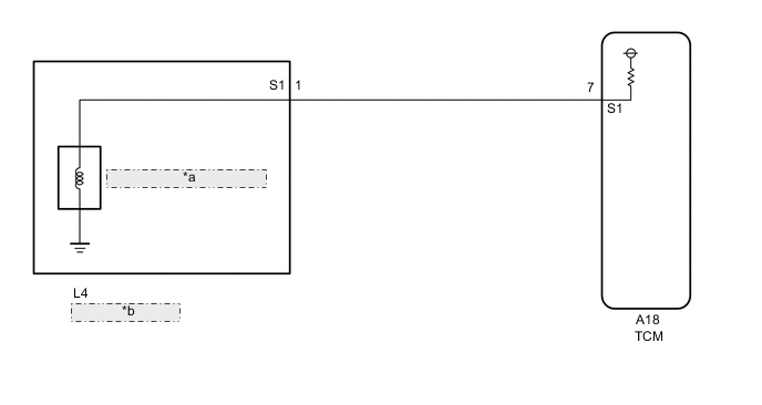
| *a | Shift Solenoid Valve S1 |
| *b | Transmission Wire |
CAUTION / NOTICE / HINT
Note
Perform the universal trip to clear permanent DTCs Click here.
-
CHECK THE SHIFT POSITION
-
Drive the vehicle with shift lever in the M.
-
Check the shift position.
Tech Tips
-
The shift solenoid valve S1 is turned on/off normally when the shift lever is in the D position:
TCM command gearshift 1st 2nd 3rd 4th 5th 6th Shift solenoid valve S1 OFF ON ON ON ON ON
-
-
PROCEDURE
-
CHECK OTHER DTCS OUTPUT
-
Connect the GTS to the DLC3.
-
Turn the ignition switch ON and push the GTS main switch ON.
-
Read the DTCs using the GTS Click here.
Result Display (DTC output) Proceed to "P0751 and P2714" or "P0752 and P0767" are output A "P0751 and P2714" or "P0752 and P0767" and other DTCs B
B 
GO TO DTC CHART Click here
A 
-
-
HYDRAULIC TEST
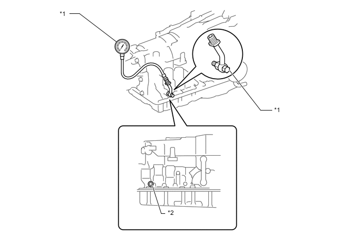
Text in Illustration *1 SST *2 Test Plug Note
-
Perform the test at the normal operating ATF (Automatic Transmission Fluid) temperature: 60 to 90°C (140 to 194°F)
-
The line pressure test should always be carried out in pairs. One technician should observe the conditions of wheels or wheel stoppers outside the vehicle while the other is performing the test.
-
Be careful to prevent SST hose from interfering with the exhaust pipe.
-
This Check must be conducted after checking and adjusting engine.
-
Perform under condition that A/C is OFF.
-
When conducting stall test, do not continue more than 5 seconds.
-
Warm up the ATF (Automatic Transmission Fluid).
-
Lift the vehicle up.
-
Remove the test plug on the transmission case center right side and connect SST.
- SST
- 09992-00095 ( 09992-00231, 09992-00271 )
-
Lower the vehicle.
-
Fully apply the parking brake and check the 4 wheels.
-
Start the engine and check idling speed.
-
Keep your left foot pressing firmly on the brake pedal and shift into D position.
-
Measure the line pressure when the engine is idling.
-
Depress the accelerator pedal all the way down. Quickly read the highest line pressure when engine speed reaches stall speed.
-
In the same manner, do the test in R position.
Specified line pressure: Condition D position kPa (kgf / cm2, psi)
R position kPa (kgf / cm2, psi)
Idling 350 to 430 kPa
(3.6 to 4.4 kgf/cm2, 51 to 62 psi)
760 to 950 kPa
(7.7 to 9.7 kgf/cm2, 110 to 138 psi)
Stall test 1200 to 1380 kPa
(12.5 to 14.0 kgf/cm2, 174 to 200 psi)
1410 to 1630 kPa
(14.4 to 16.6 kgf/cm2, 204 to 236 psi)
NG
REPLACE SHIFT SOLENOID VALVE SLT Click here
OK
-
-
INSPECT SHIFT SOLENOID VALVE S1
-
Remove the shift solenoid valve S1 Click here.
-
Perform inspection of the shift solenoid valve S1 Click here.
NG
REPLACE SHIFT SOLENOID VALVE S1 Click here
OK
-
-
INSPECT TRANSMISSION VALVE BODY ASSEMBLY
-
Perform inspection of the transmission valve body assembly Click here.
OK There are no foreign objects on each valve.
OK
REPLACE AUTOMATIC TRANSMISSION ASSEMBLY Click here
NG
REPLACE TRANSMISSION VALVE BODY ASSEMBLY Click here
-