AUTOMATIC HIGH BEAM MAIN SWITCH REMOVAL

Tech Tips
-
Use the same procedure for RHD and LHD vehicles.
-
The procedure listed below is for LHD vehicles.
-
REMOVE FRONT DOOR SCUFF PLATE LH
-
Place your hands on the inner portion of the front door scuff plate LH and detach the 2 claws labeled A, 6 claws labeled B and 2 claws labeled C in the order shown in the illustration.
-
Raise the front door scuff plate LH to detach the 4 clips on the outer side and remove it.
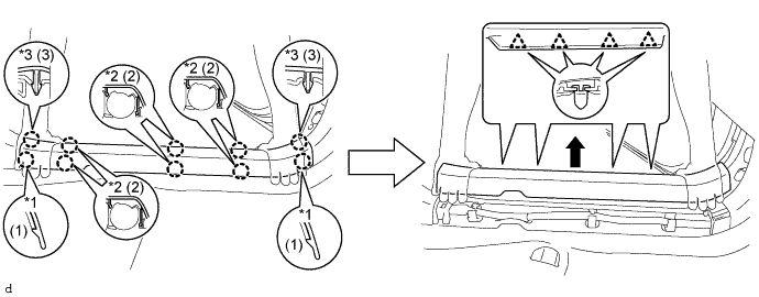
Text in Illustration *1 Claw A *2 Claw B *3 Claw C - -
-
-
REMOVE FRONT DOOR OPENING TRIM COVER LH
-
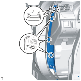
Detach the 5 claws and remove the front door opening trim cover LH.
-
-
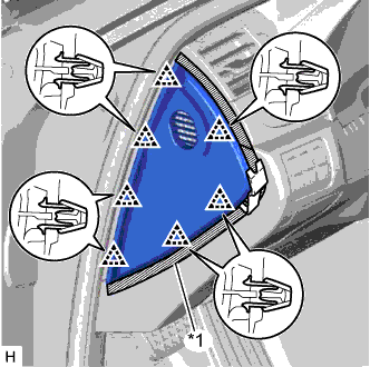
REMOVE CENTER INSTRUMENT CLUSTER FINISH PANEL
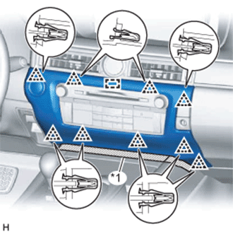
Text in Illustration *1 Protective Tape
-
Put protective tape around the center instrument cluster finish panel.
-
Detach the 9 clips and guide.
-
Disconnect the connector and remove the center instrument cluster finish panel.
-
-
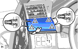
REMOVE INSTRUMENT PANEL FINISH PANEL END LH
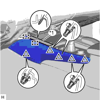
Text in Illustration *1 Protective Tape
-
Put protective tape around the instrument panel finish panel end LH.
-
Detach the 5 clips and 2 guides and remove the instrument panel finish panel end LH.
-
-
REMOVE INSTRUMENT SIDE PANEL LH
Text in Illustration *1 Protective Tape
-
Put protective tape around the instrument side panel LH.
-
Using a moulding remover, detach the 7 clips and remove the instrument side panel LH.
-
-
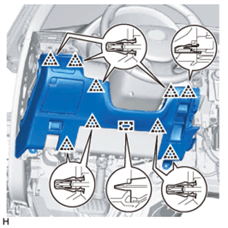
REMOVE NO. 1 INSTRUMENT PANEL GARNISH SUB-ASSEMBLY
Text in Illustration *1 Protective Tape
-
Put protective tape around the No. 1 instrument panel garnish sub-assembly.
-
Using a moulding remover, detach the 4 clips and remove the No. 1 instrument panel garnish sub-assembly.
-
-
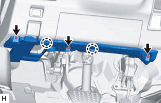
REMOVE NO. 1 INSTRUMENT PANEL UNDER COVER SUB-ASSEMBLY
-
Remove the 3 screws <A>.
-
Detach the 2 claws.
-
Disconnect the connectors, detach the clamp and remove the No. 1 instrument panel under cover sub-assembly.
-
-
REMOVE NO. 1 INSTRUMENT PANEL SAFETY PAD SUB-ASSEMBLY
-
Detach the 9 clips and guide.
-
Disconnect the connectors and remove the No. 1 instrument panel safety pad sub-assembly.
-
-
REMOVE INTEGRATION CONTROL AND PANEL ASSEMBLY
-
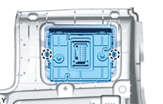
Disengage the 2 claws and remove the integration control and panel assembly.
-