HAZARD WARNING SWITCH REMOVAL

-
PRECAUTION
Note
-
After turning the power switch off, waiting time may be required before disconnecting the cable from the auxiliary battery terminal. Therefore, make sure to read the disconnecting the cable from the auxiliary battery terminal notice before proceeding with work Click here.
-
When replacing the multi-media module receiver assembly or DCM (telematics transceiver), perform the vehicle contract setting Click here.
-
The safety connect device uses the DCM (telematics transceiver) to provide access to the network service.
-
The telematics transceiver has a DCM ID (described on the label attached to the DCM (telematics transceiver)).
-
-
REMOVE LUGGAGE COMPARTMENT FLOOR MAT
-
Remove the luggage compartment floor mat.
-
-
REMOVE LUGGAGE COMPARTMENT TRIM COVER LH
-
Remove the luggage compartment trim cover LH.
-
-
DISCONNECT CABLE FROM AUXILIARY BATTERY NEGATIVE TERMINAL
Note
When disconnecting the cable, some systems need to be initialized after the cable is reconnected Click here.
-
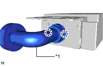
REMOVE CENTER INSTRUMENT CLUSTER FINISH PANEL
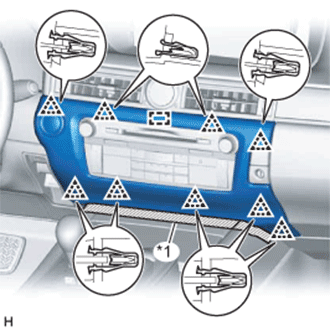
Text in Illustration *1 Protective Tape
-
Put protective tape around the center instrument cluster finish panel.
-
Detach the 9 clips and guide.
-
Disconnect the connector and remove the center instrument cluster finish panel.
-
-
REMOVE MULTI-MEDIA MODULE RECEIVER ASSEMBLY WITH BRACKET
-
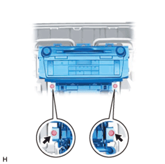
Remove the 2 screws.
-
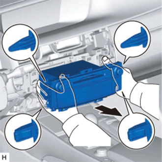
Detach the 2 claws and 2 clips.
-
Pull out the multi-media module receiver assembly with bracket.
-
Disconnect the connectors and remove the multi-media module receiver assembly with bracket.
-
-
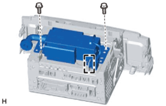
REMOVE NO. 1 ION GENERATOR SUB-ASSEMBLY
-
Detach the claw.
-
Remove the 2 screws and No. 1 ion generator sub-assembly.
-
Text in Illustration *1 Rear Air Duct Sub-assembly Detach the 2 claws and remove the rear air duct sub-assembly.
-
-
REMOVE NO. 1 RADIO BRACKET
-
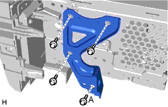
Remove the screw labeled A and ion generator bracket.
-
Remove the 3 screws and No. 1 radio bracket.
-
-
REMOVE NO. 2 RADIO BRACKET
-
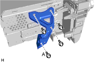
Remove the screw labeled A and ion generator bracket.
-
Remove the 4 screws and No. 2 radio bracket.
-