HEADLIGHT ASSEMBLY (for HID Headlight) REASSEMBLY

Tech Tips
-
Use the same procedure for the RH and LH sides.
-
The procedure listed below is for the LH side.
-
INSTALL HEADLIGHT SWIVEL MOTOR LH
-

Move the headlight swivel motor LH as shown in the illustration to engage the gears.
-
Install the screw.
-
Push a unit into the 2 aiming screws from the front, and turn the 2 aiming screws clockwise.
-
Turn the 2 aiming screws so that dimension the same as measured before removing.
-
Engage the gears, and install the plate with the 2 screws.
-
Connect the connector.
-
Install the aluminum surfaces with the 2 screws to the headlight unit.
Note
-
Do not touch the the aluminum surfaces with bare hands.
-
If there are fingerprints on the aluminum surfaces, wipe them off with a soft cloth.
-
-
-
INSTALL HEADLIGHT SUB-ASSEMBLY LH (w/ Night View System)
-
Push a unit into the aiming screw from the front, and turn the aiming screw clockwise.
Note
-
Do not touch the the aluminum surfaces with bare hands.
-
If there are fingerprints on the aluminum surfaces, wipe them off with a soft cloth.
-
-
Turn the aiming screw so that dimensions the same as measured before removing.
-
Install the headlight sub-assembly LH with the 2 screws to the headlight unit.
-
Connect the 2 connectors.
-
Install the gear with the 3 screws to the headlight unit.
Note
Make sure that the gear and aiming screw are properly engaged.
-
Engage the gears, and install the plate with the 2 screws.
-
Install the 2 screws.
-
Install the aluminum surfaces with the 2 screws to the headlight unit.
Note
-
Do not touch the the aluminum surfaces with bare hands.
-
If there are fingerprints on the aluminum surfaces, wipe them off with a soft cloth.
-
-
-
INSTALL LIGHT CONTROL ECU
-
Connect the connector.
-
Install the light control ECU with the 2 screws to the headlight unit.
-
-
INSTALL LIGHT FAILURE INDICATOR SENSOR (w/ Night View System)
-
Connect the connector.
-
Install the light failure indicator sensor with the 2 screws to the headlight unit.
-
-
INSTALL HEADLIGHT UNIT LH
-
Connect the connector.
-
Install the headlight unit LH with the 3 screws to the headlight unit.
Note
-
Do not touch the the aluminum surfaces with bare hands.
-
If there are fingerprints on the aluminum surfaces, wipe them off with a soft cloth.
-
-
-
INSTALL HEADLIGHT LENS GASKET
-
Completely remove the old headlight lens gasket.
-
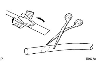
Partially remove the peeling paper, and cut off a piece of it.
-
Fold the peeling paper over the tip of a screwdriver and fix it in place with tape.
Note
Use the peeling paper that is supplied with the seal.
-
Using scissors, cut the end of the seal at a diagonal (45°).
-
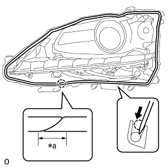
Set the seal into the groove so that the ends of the seal are aligned with the bottom of the headlight, as shown in the illustration.
-
Using the screwdriver, completely press the seal into the headlight to install the seal.
-
After pressing the seal completely, cut the seal ends at a diagonal (45°) so that the ends overlap for 10 mm (0.394 in.) or more.
Text in Illustration *a 10 mm (0.394 in.)
-
-
INSTALL HEADLIGHT LENS LH
-
Attach the 8 claws to install the headlight lens LH.
Note
-
Wear rubber gloves when handling the headlight lens LH.
-
Do not touch the headlight lens LH or the aluminum surfaces with bare hands.
-
If there are fingerprints on the aluminum surfaces, wipe them off with a soft cloth.
-
If there are fingerprints on the back of the lens, replace the headlight lens LH.
-
Do not allow dirt or foreign matter on the headlight lens LH.
-
-
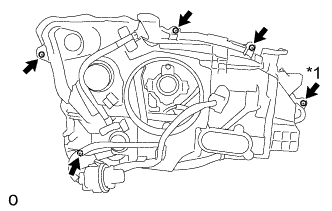
Text in Illustration *1 "TORX" Screw Install the 4 screws.
-
Using a T20H "TORX" driver, install the "TORX" screw.
-
-
INSTALL NO. 2 FRONT BUMPER SIDE SUPPORT LH
-
Install the No. 2 front bumper side support LH with the 2 screws to the headlight unit.
-
-
INSTALL FRONT BUMPER SIDE SUPPORT LH
-
Install the front bumper side support LH with the 2 screws to the headlight unit.
-
-
INSTALL DISCHARGE HEADLIGHT BULB
-
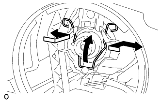
Lock the set spring as shown in the illustration to install the discharge headlight bulb to the headlight unit.
Note
Do not touch the discharge headlight bulb glass.
-
-
INSTALL HEADLIGHT GASKET
-
Install a new headlight gasket to the headlight light control ECU sub-assembly LH.
-
-
INSTALL HEADLIGHT LIGHT CONTROL ECU SUB-ASSEMBLY LH
-
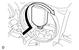
Turn the headlight light control ECU sub-assembly LH socket in the direction indicated by the arrow in the illustration to connect the headlight light control ECU sub-assembly LH socket.
Note
-
Check that the headlight gasket is installed on the headlight light control ECU subassembly LH.
-
Check that the headlight gasket is not damaged or contaminated with foreign matter. If there is any damage, replace the headlight gasket with a new one.
-
Do not pull the headlight light control ECU sub-assembly LH with the socket connected.
-
-
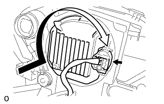
Turn the headlight light control ECU sub-assembly LH in the direction indicated by the arrow in the illustration to install the headlight light control ECU sub-assembly LH to the headlight unit.
-
Connect the connector.
-
-
INSTALL FRONT TURN SIGNAL LIGHT BULB
-
Install the front turn signal light bulb to the front turn signal light socket.
-
-
INSTALL FRONT TURN SIGNAL LIGHT SOCKET
-
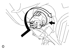
Turn the front turn signal light socket in the direction indicated by the arrow in the illustration to install the front turn signal light socket.
-
Connect the connector.
-