LIGHTING SYSTEM Headlight (HI-BEAM) Circuit
DESCRIPTION
The main body ECU receives headlight dimmer switch information signals and illuminates the high beam headlights.
WIRING DIAGRAM
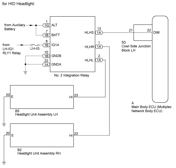
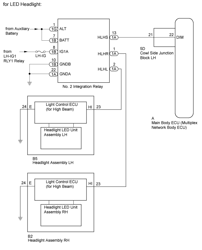
INSPECTION PROCEDURE
Note
-
Inspect the bulbs and fuses for circuits related to this system before performing the following inspection procedure.
-
Recognition code registration is necessary when replacing the main body ECU (multiplex network body ECU).
-
If the main body ECU (multiplex network body ECU) is replaced, refer to the Service Bulletin.
PROCEDURE
-
PERFORM ACTIVE TEST USING GTS (HEADLIGHT)
-
Using the GTS, perform the Active Test Click here.
Main Body Tester Display Test Part Control Range Diagnostic Note Head Light Hi Headlight dimmer relay ON/OFF - OK High beam headlights come on.
NG 
CHECK HARNESS AND CONNECTOR (NO. 2 INTEGRATION RELAY - BATTERY AND BODY GROUND) Click here
OK 
REPLACE MAIN BODY ECU (MULTIPLEX NETWORK BODY ECU) Click here
-
-
CHECK HARNESS AND CONNECTOR (NO. 2 INTEGRATION RELAY - BATTERY AND BODY GROUND)
-
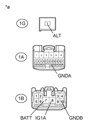
Text in Illustration *a Front view of wire harness connector
(to No. 2 Integration Relay)
Disconnect the No. 2 integration relay connectors.
-
Measure the voltage according to the value(s) in the table below.
Standard Voltage Tester Connection Condition Specified Condition 1G-1 (ALT) - Body ground Always 11 to 14 V 1B-7 (BATT) - Body ground 1B-8 (IG1A) - Body ground Power switch on (IG) -
Measure the resistance according to the value(s) in the table below.
Standard Resistance Tester Connection Condition Specified Condition 1B-10 (GNDB) - Body ground Always Below 1 Ω 1A-22 (GNDA) - Body ground
NG 
REPAIR OR REPLACE HARNESS OR CONNECTOR
OK 
-
-
CHECK HARNESS AND CONNECTOR (NO. 2 INTEGRATION RELAY - COWL SIDE JUNCTION BLOCK LH)
-
Disconnect the 1A No. 2 integration relay connector.
-
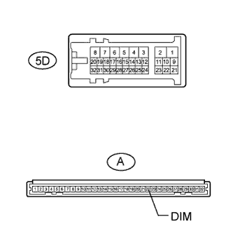
Disconnect the 5D cowl side junction block LH connector.
-
Measure the resistance according to the value(s) in the table below.
Standard Resistance Tester Connection Condition Specified Condition 1A-13 (HLHS) - 5D-21 Always Below 1 Ω 1A-13 (HLHS) - Body ground Always 10 kΩ or higher
NG
REPAIR OR REPLACE HARNESS OR CONNECTOR
OK
-
-
INSPECT COWL SIDE JUNCTION BLOCK LH
-
Remove the cowl side junction block LH Click here.
-
Remove the main body ECU from the cowl side junction block LH Click here.
-
Measure the resistance according to the value(s) in the table below.
Standard Resistance Tester Connection Condition Specified Condition A-22 (DIM) - 5D-21 Always Below 1 Ω
NG
REPLACE COWL SIDE JUNCTION BLOCK LH Click here
OK
PROCEED TO NEXT SUSPECTED AREA SHOWN IN PROBLEM SYMPTOMS TABLE Click here
-