LIGHTING SYSTEM Headlight Relay Circuit
DESCRIPTION
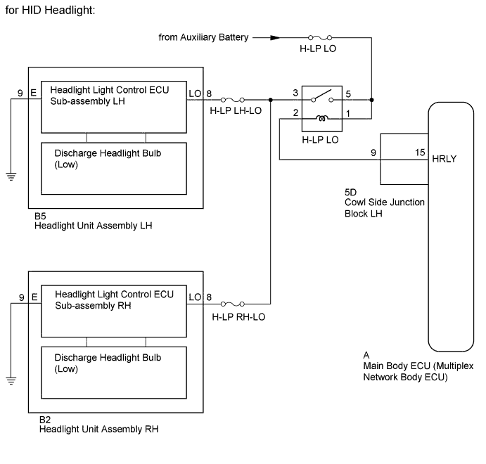
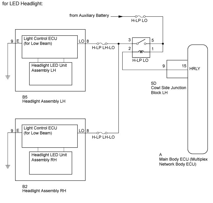
The main body ECU receives headlight dimmer switch information signals and illuminates the low beam headlights.
WIRING DIAGRAM
INSPECTION PROCEDURE
Note
-
Inspect the bulbs and fuses for circuits related to this system before performing the following inspection procedure.
-
Recognition code registration is necessary when replacing the main body ECU (multiplex network body ECU).
-
If the main body ECU (multiplex network body ECU) is replaced, refer to the Service Bulletin.
PROCEDURE
-
PERFORM ACTIVE TEST USING GTS (H-LP LO RELAY)
-
Using the GTS, perform the Active Test Click here.
Main Body Tester Display Test Part Control Range Diagnostic Note Headlight Relay Low beam headlight relay ON/OFF - OK Headlight relay operates (low beam headlights come on).
NG 
INSPECT HEADLIGHT RELAY (H-LP LO) Click here
OK 
REPLACE MAIN BODY ECU (MULTIPLEX NETWORK BODY ECU) Click here
-
-
INSPECT HEADLIGHT RELAY (H-LP LO)
-
Remove the headlight relay from the No. 1 engine room relay block and junction block.
-
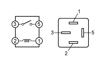
Measure the resistance according to the value(s) in the table below.
Standard Resistance Tester Connection Condition Specified Condition 3 - 5 Battery voltage not applied between terminals 1 and 2 10 kΩ or higher 3 - 5 Battery voltage applied between terminals 1 and 2 Below 1 Ω
NG 
REPLACE HEADLIGHT RELAY (H-LP LO RELAY)
OK 
-
-
CHECK HARNESS AND CONNECTOR (HEADLIGHT RELAY [H-LP LO] - BATTERY)
-
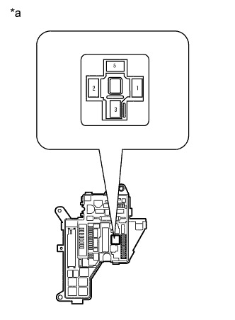
Text in Illustration *a Front view of wire harness connector
(to Headlight Relay)
Remove the headlight relay from the No. 1 engine room relay block and junction block.
-
Measure the voltage according to the value(s) in the table below.
Standard Voltage Tester Connection Condition Specified Condition Headlight relay terminal 5 - Body ground Always 11 to 14 V Headlight relay terminal 1 - Body ground
NG
REPAIR OR REPLACE HARNESS OR CONNECTOR
OK
-
-
CHECK HARNESS AND CONNECTOR (HEADLIGHT RELAY [H-LP LO] - COWL SIDE JUNCTION BLOCK LH)
-
Remove the headlight relay from the No. 1 engine room relay block and junction block.
-
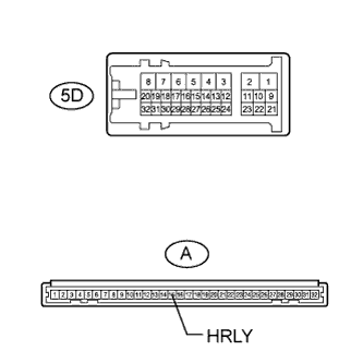
Disconnect the 5D cowl side junction block LH connector.
-
Measure the resistance according to the value(s) in the table below.
Standard Resistance Tester Connection Condition Specified Condition Headlight relay terminal 2 - 5D-9 Always Below 1 Ω 5D-9 - Body ground Always 10 kΩ or higher
NG
REPAIR OR REPLACE HARNESS OR CONNECTOR
OK
-
-
INSPECT COWL SIDE JUNCTION BLOCK LH
-
Remove the cowl side junction block LH Click here.
-
Remove the main body ECU from the cowl side junction block LH Click here.
-
Measure the resistance according to the value(s) in the table below.
Standard Resistance Tester Connection Condition Specified Condition A-15 (HRLY) - 5D-9 Always Below 1 Ω
NG
REPLACE COWL SIDE JUNCTION BLOCK LH Click here
OK
PROCEED TO NEXT SUSPECTED AREA SHOWN IN PROBLEM SYMPTOMS TABLE Click here
-