LIGHTING SYSTEM, Diagnostic DTC:B2430, B2431

| DTC Code | DTC Name |
|---|---|
| B2430 | LED Headlight LH Circuit Malfunction |
| B2431 | LED Headlight RH Circuit Malfunction |
DESCRIPTION
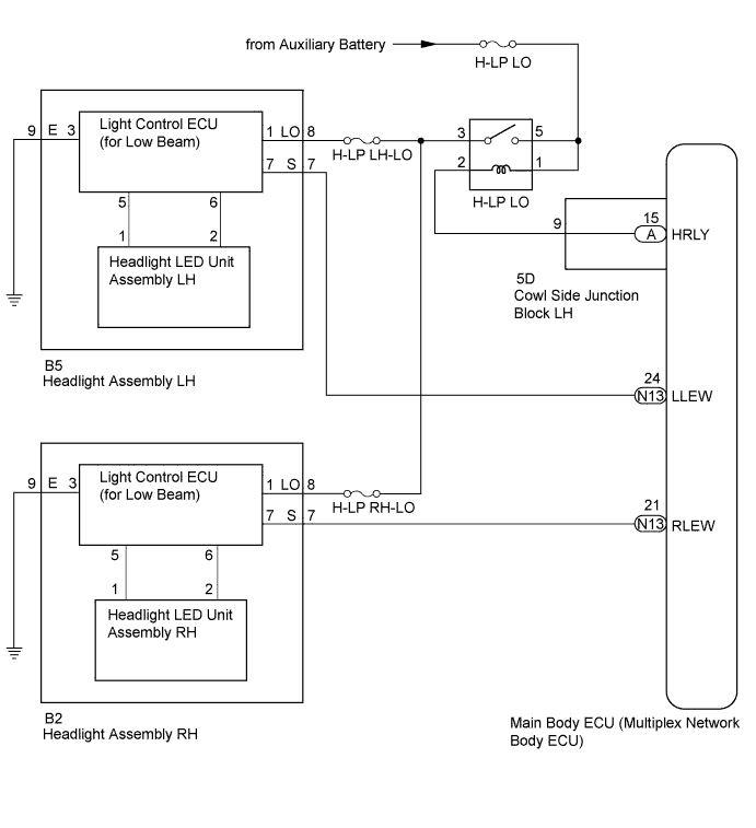
The illumination of the low beam headlights is controlled by the main body ECU. When the headlights are turned on, the main body ECU receives a signal from the headlight assembly and detects the illumination condition of the low beam headlights.
| DTC Code | DTC Detection Condition | Trouble Area |
|---|---|---|
| B2430 | LED headlight LH circuit malfunction |
|
| B2431 | LED headlight RH circuit malfunction |
|
Tech Tips
DTC B2430 and B2431 are not output if 12 seconds have not elapsed since the power switch was turned on (IG).
WIRING DIAGRAM
INSPECTION PROCEDURE
Note
-
Inspect the fuses for circuits related to this system before performing the following inspection procedure.
-
If the main body ECU (multiplex network body ECU) is replaced, refer to the Service Bulletin.
PROCEDURE
-
CLEAR DTC
-
Clear the DTCs Click here.
NEXT 
-
-
CHECK FOR DTC
-
Check for DTCs Click here.
OK DTC B2430 or B2431 output does not occur.
NG 
INSPECT HEADLIGHT RELAY (H-LP LO) Click here
OK 
USE SIMULATION METHOD TO CHECK Click here
-
-
INSPECT HEADLIGHT RELAY (H-LP LO)
-
Remove the headlight relay from the No. 1 engine room relay block and junction block.
-
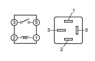
Measure the resistance according to the value(s) in the table below.
Standard Resistance Tester Connection Condition Specified Condition 3 - 5 Battery voltage not applied between terminals 1 and 2 10 kΩ or higher 3 - 5 Battery voltage applied between terminals 1 and 2 Below 1 Ω
NG 
REPLACE HEADLIGHT RELAY (H-LP LO)
OK
-
-
CHECK HARNESS AND CONNECTOR (HEADLIGHT RELAY [H-LP LO] - BATTERY)
-
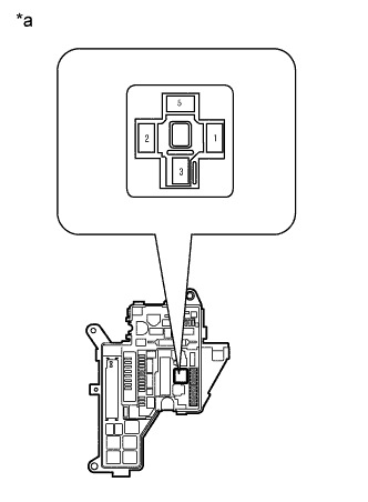
Text in Illustration *a Front view of wire harness connector
(to Headlight Relay)
Remove the headlight relay from the No. 1 engine room relay block and junction block.
-
Measure the voltage according to the value(s) in the table below.
Standard Voltage Tester Connection Condition Specified Condition Headlight relay terminal 5 - Body ground Always 11 to 14 V Headlight relay terminal 1 - Body ground
NG
REPAIR OR REPLACE HARNESS OR CONNECTOR
OK
-
-
CHECK HARNESS AND CONNECTOR (HEADLIGHT RELAY [H-LP LO] - COWL SIDE JUNCTION BLOCK LH)
-
Remove the headlight relay from the No. 1 engine room relay block and junction block.
-
Disconnect the 5D cowl side junction block LH connector.
-
Measure the resistance according to the value(s) in the table below.
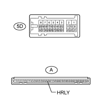
Standard Resistance Tester Connection Condition Specified Condition Headlight relay terminal 2 - 5D-9 Always Below 1 Ω 5D-9 - Body ground Always 10 kΩ or higher
NG
REPAIR OR REPLACE HARNESS OR CONNECTOR
OK
-
-
INSPECT COWL SIDE JUNCTION BLOCK LH
-
Remove the cowl side junction block LH Click here.
-
Remove the main body ECU from the cowl side junction block LH Click here.
-
Measure the resistance according to the value(s) in the table below.
Standard Resistance Tester Connection Condition Specified Condition A-15 (HRLY) - 5D-9 Always Below 1 Ω
NG
REPLACE COWL SIDE JUNCTION BLOCK LH Click here
OK
-
-
CHECK HARNESS AND CONNECTOR (HEADLIGHT RELAY [H-LP LO] - HEADLIGHT)
-
Remove the headlight relay from the No. 1 engine room relay block and junction block.
-
Disconnect the B5*1 or B2*2 headlight connector.
-
*1: for LH
-
*2: for RH
-
-
Measure the resistance according to the value(s) in the table below.
Standard Resistance for LH Tester Connection Condition Specified Condition Headlight relay terminal 3 - B5-8 (LO) Always Below 1 Ω Headlight relay terminal 3 - Body ground Always 10 kΩ or higher for RH Tester Connection Condition Specified Condition Headlight relay terminal 3 - B2-8 (LO) Always Below 1 Ω Headlight relay terminal 3 - Body ground Always 10 kΩ or higher
NG
REPAIR OR REPLACE HARNESS OR CONNECTOR
OK
-
-
CHECK HARNESS AND CONNECTOR (HEADLIGHT - MAIN BODY ECU AND BODY GROUND)
-
Disconnect the B5*1 or B2*2 headlight unit connector.
-
*1: for LH
-
*2: for RH
-
-
Disconnect the N13 main body ECU connector.
-
Measure the resistance according to the value(s) in the table below.
Standard Resistance for LH Tester Connection Condition Specified Condition B5-7 (S) - N13-24 (LLEW) Always Below 1 Ω B5-9 (E) - Body ground Below 1 Ω B5-7 (S) - Body ground 10 kΩ or higher for RH Tester Connection Condition Specified Condition B2-7 (S) - N13-21 (RLEW) Always Below 1 Ω B2-9 (E) - Body ground Below 1 Ω B2-7 (S) - Body ground 10 kΩ or higher
NG
REPAIR OR REPLACE HARNESS OR CONNECTOR
OK
-
-
INSPECT HEADLIGHT ASSEMBLY
-
Remove the headlight Click here.
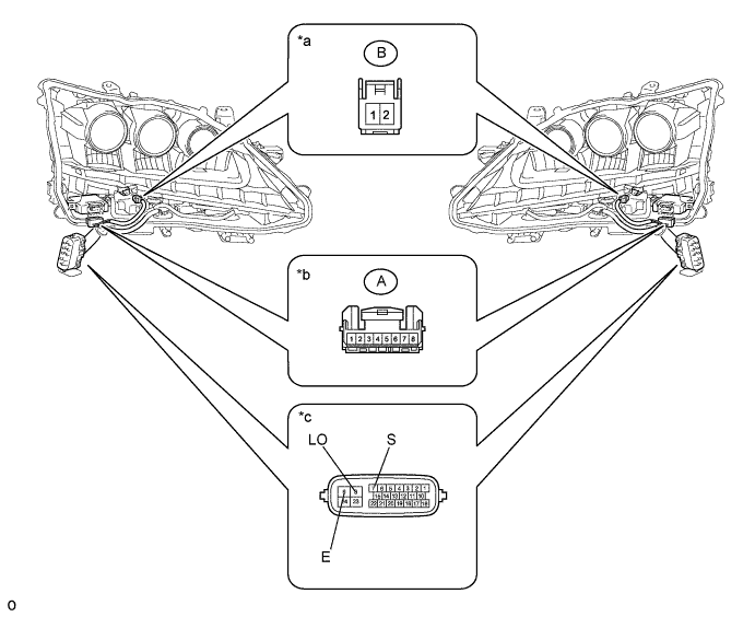
Text in Illustration *a Front view of wire harness connector
(to Headlight LED Unit Assembly)
*b Front view of wire harness connector
(to Light Control ECU [for Low Beam])
*c Component without harness connected
(Headlight Assembly)
- - -
Remove the headlight lens Click here.
-
Disconnect the light control ECU (for low beam) connector.
-
Disconnect the headlight LED unit connector.
-
Measure the resistance according to the value(s) in the table below.
Standard Resistance Tester Connection Condition Specified Condition 8 (LO) - A-1 Always Below 1 Ω 7 (S) - A-7 9 (E) - A-3 A-5 - B-1 A-6 - B-2
NG
REPLACE HEADLIGHT ASSEMBLY Click here
OK
-
-
CHECK LIGHT CONTROL ECU (FOR LOW BEAM)
-
Temporarily replace the light control ECU (for low beam) with a new or normally functioning one Click here.
-
Check for DTCs Click here.
OK DTC B2430 or B2431 output does not occur.
NG
CHECK HEADLIGHT LED UNIT ASSEMBLY Click here
OK
END (LIGHT CONTROL ECU [FOR LOW BEAM] WAS DEFECTIVE)
-
-
CHECK HEADLIGHT LED UNIT ASSEMBLY
-
Temporarily replace the headlight LED unit with a new or normally functioning one Click here.
-
Check for DTCs Click here.
OK DTC B2430 or B2431 output does not occur.
NG
REPLACE MAIN BODY ECU (MULTIPLEX NETWORK BODY ECU) Click here
OK
END (HEADLIGHT LED UNIT WAS DEFECTIVE)
-