LIGHTING SYSTEM, Diagnostic DTC:B1244

| DTC Code | DTC Name |
|---|---|
| B1244 | Light Sensor Circuit Malfunction |
DESCRIPTION
The automatic light control sensor detects ambient light, converts it into an electrical signal and outputs it to the main body ECU. The main body ECU turns the headlights and taillights on or off according to the signal.
| DTC Code | DTC Detection Condition | Trouble Area |
|---|---|---|
| B1244 |
|
|
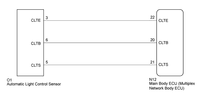
WIRING DIAGRAM
INSPECTION PROCEDURE
Note
-
Recognition code registration is necessary when replacing the main body ECU (multiplex network body ECU).
-
If the main body ECU (multiplex network body ECU) is replaced, refer to the Service Bulletin.
PROCEDURE
-
CLEAR DTC
-
Clear the DTCs Click here.
NEXT 
-
-
CHECK FOR DTC
-
Check for DTCs Click here.
OK DTC B1244 output does not occur.
NG 
READ VALUE USING GTS (AUTOMATIC LIGHT CONTROL SENSOR) Click here
OK 
USE SIMULATION METHOD TO CHECK Click here
-
-
READ VALUE USING GTS (AUTOMATIC LIGHT CONTROL SENSOR)
-
Using the GTS, read the Data List Click here.
Main Body Tester Display Measurement Item/Range Normal Condition Diagnostic Note Illumination Rate Info Illumination rate information / 0 ms. to 99.99 ms. Value output according to ambient light levels - OK Normal condition listed above is displayed.
NG
CHECK HARNESS AND CONNECTOR (MAIN BODY ECU - AUTOMATIC LIGHT CONTROL SENSOR) Click here
OK
REPLACE MAIN BODY ECU (MULTIPLEX NETWORK BODY ECU) Click here
-
-
CHECK HARNESS AND CONNECTOR (MAIN BODY ECU - AUTOMATIC LIGHT CONTROL SENSOR)
-
Disconnect the N12 main body ECU connector.
-
Disconnect the O1 automatic light control sensor connector.
-
Measure the resistance according to the value(s) in the table below.
Standard Resistance Tester Connection Condition Specified Condition N12-22 (CLTE) - O1-3 (CLTE) Always Below 1 Ω N12-21 (CLTS) - O1-5 (CLTS) Always Below 1 Ω N12-20 (CLTB) - O1-6 (CLTB) Always Below 1 Ω N12-22 (CLTE) - Body ground Always 10 kΩ or higher N12-21 (CLTS) - Body ground Always 10 kΩ or higher N12-20 (CLTB) - Body ground Always 10 kΩ or higher
NG 
REPAIR OR REPLACE HARNESS OR CONNECTOR
OK
-
-
CHECK MAIN BODY ECU (MULTIPLEX NETWORK BODY ECU)
-
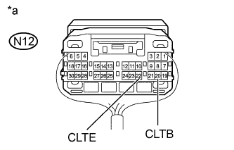
Text in Illustration *a Component with harness connected
(Main Body ECU [Multiplex Network Body ECU])
Remove the cowl side junction block LH and main body ECU as a unit with the connectors still connected Click here.
-
Measure the voltage according to the value(s) in the table below.
Standard Voltage Tester Connection Switch Condition Specified Condition N12-20 (CLTB) - N12-22 (CLTE) Power switch off Below 1 V Power switch on (IG) 11 to 14 V
NG
REPLACE MAIN BODY ECU (MULTIPLEX NETWORK BODY ECU) Click here
OK
-
-
CHECK AUTOMATIC LIGHT CONTROL SENSOR
-
Check the automatic light control sensor Click here.
NG
REPLACE AUTOMATIC LIGHT CONTROL SENSOR Click here
OK
REPLACE MAIN BODY ECU (MULTIPLEX NETWORK BODY ECU) Click here
-