WIPER SWITCH REMOVAL

Tech Tips
-
Use the same procedure for RHD and LHD vehicles.
-
The procedure listed below is for LHD vehicles.
-
Use the same procedure for the RH and LH sides.
-
PRECAUTION
Note
After turning the power switch off, waiting time may be required before disconnecting the cable from the auxiliary battery terminal. Therefore, make sure to read the disconnecting the cable from the auxiliary battery terminal notice before proceeding with work Click here.
-
REMOVE LUGGAGE COMPARTMENT FLOOR MAT
-
Remove the luggage compartment floor mat.
-
-
REMOVE LUGGAGE COMPARTMENT TRIM COVER LH
-
Remove the luggage compartment trim cover.
-
-
DISCONNECT CABLE FROM AUXILIARY BATTERY NEGATIVE TERMINAL
-
Disable the auto away/return function by changing the customize parameter Click here.
Note
Record the current customize parameter setting (whether the auto away/return function is enabled or disabled) in order to restore the current setting after finishing this operation.
Tech Tips
Performing the above operation disables the auto away/return function when the power switch is turned off.
-
Turn the power switch on (IG). Operate the tilt and telescopic switch to fully extend and lower the steering column assembly.
-
Turn the power switch off and disconnect the cable from the auxiliary battery negative (-) terminal.
Note
When disconnecting the cable, some systems need to be initialized after the cable is reconnected Click here.
-
-
REMOVE STEERING COLUMN COVER
Note
Removing the lower steering column cover in the incorrect order will cause the parts to break.
-
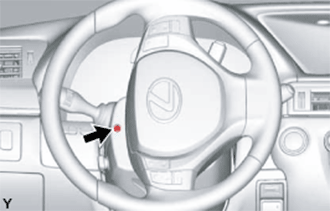
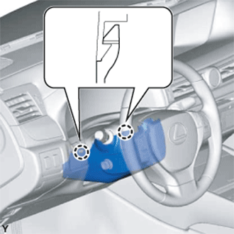
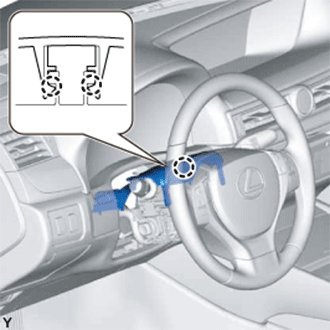
Turn the steering wheel assembly to the left and remove the screw.
-
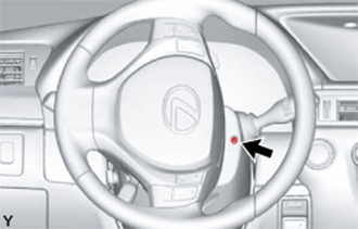
Turn the steering wheel assembly to the right and remove the screw.
-
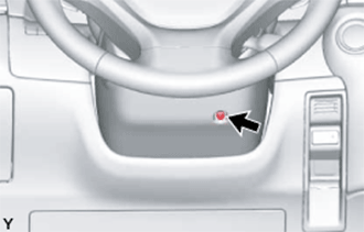
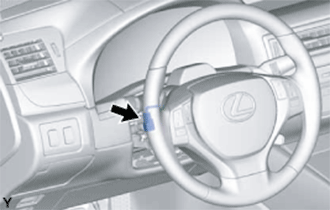
Remove the screw as shown in the illustration.
-
Push the right and left sides of the lower steering column cover to disengage the 2 claws.
-
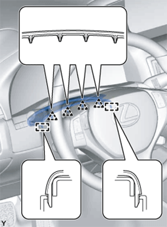
Disengage the 4 clips and 2 guides to separate the instrument panel cluster finish panel from the upper steering column cover.
-
w/ Driver Monitor Camera:
-
Disconnect the connector.
-
-
Disengage the 2 claws and remove the upper steering column cover.
-
-
REMOVE WINDSHIELD WIPER SWITCH ASSEMBLY
-
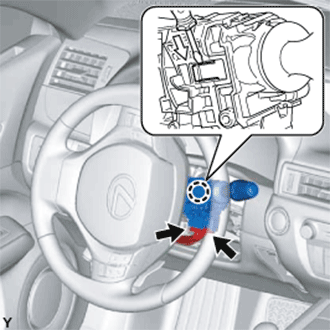
Disconnect each connector.
-
Disengage the claw and remove the windshield wiper switch assembly as shown in the illustration.
Note
Be careful not to damage the claw.
-