LUGGAGE COMPARTMENT DOOR DISASSEMBLY

-
REMOVE LUGGAGE LOCK CONTROL CABLE PLATE (w/ Handle)
-
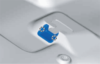
Detach the 2 claws and remove the luggage lock control cable plate.
-
-
REMOVE LUGGAGE COMPARTMENT DOOR INSIDE HANDLE (w/ Handle)
-
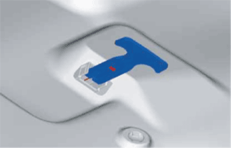
Disconnect the luggage compartment door inside handle from the luggage door lock control cable sub-assembly.
-
-
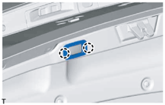
REMOVE LUGGAGE COMPARTMENT DOOR ASSIST GRIP
-
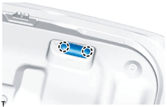
Detach the 2 claws and open the cover.
-
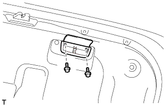
Remove the 2 screws and luggage compartment door assist grip.
-
-
REMOVE SWITCH BEZEL (w/ Power Trunk Lid System)
-
Detach the 2 claws and remove the switch bezel.
-
-
REMOVE LUGGAGE COMPARTMENT DOOR COVER
-
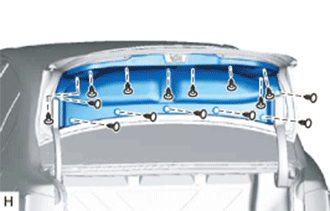
Remove the 15 clips and luggage compartment door cover.
-
-
REMOVE LUGGAGE COMPARTMENT TRIM INNER COVER LH
-
REMOVE LUGGAGE COMPARTMENT TRIM INNER COVER RH
-
REMOVE LUGGAGE COMPARTMENT DOOR HINGE COVER LH
-
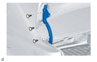
Remove the 3 clips and luggage compartment door hinge cover LH.
-
-
REMOVE LUGGAGE COMPARTMENT DOOR HINGE COVER RH
-
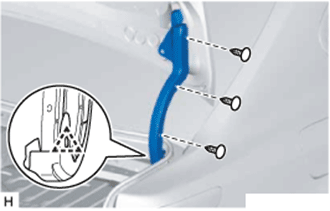
Remove the 3 clips.
-
Detach the clip and remove the luggage compartment door hinge cover RH.
-
-
REMOVE DOOR CONTROL SWITCH (w/ Power Trunk Lid System)
-
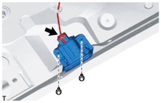
Disconnect the connector.
-
Remove the 2 bolts and door control switch.
-
-
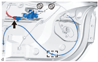
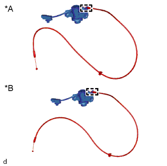
REMOVE LUGGAGE DOOR LOCK CONTROL CABLE SUB-ASSEMBLY (w/ Handle)
-
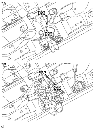
Text in Illustration *A w/o Power Trunk Lid System *B w/ Power Trunk Lid System Detach the clamp of the luggage compartment door lock assembly and the clamp of the luggage lock control cable clamp and remove the luggage door lock control cable sub-assembly.
-
-
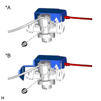
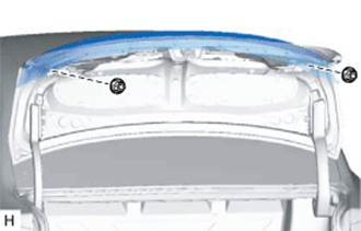
REMOVE LUGGAGE COMPARTMENT DOOR LOCK ASSEMBLY
-
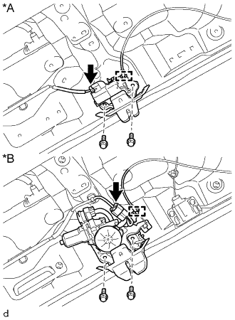
Text in Illustration *A w/o Power Trunk Lid System *B w/ Power Trunk Lid System Disconnect the connector.
-
Disconnect the luggage door lock control cable sub-assembly.
-
Remove the 2 bolts and luggage compartment door lock assembly.
-
-
REMOVE LUGGAGE LOCK CONTROL CABLE CLAMP (w/ Handle)
-
Detach the claw and guide and remove the luggage lock control cable clamp.
-
-
REMOVE LUGGAGE COMPARTMENT DOOR LOCK CYLINDER ASSEMBLY
-
Disconnect the connector.
-
Detach the clamp of the luggage door lock control cable sub-assembly.
-
Remove the 2 nuts and luggage compartment door lock cylinder assembly together with the luggage door lock control cable sub-assembly.
-
-
REMOVE LUGGAGE COMPARTMENT KEY CYLINDER PROTECTOR
-
Text in Illustration *A for Type A *B for Type B Remove the nut and luggage compartment key cylinder protector.
-
-
REMOVE LUGGAGE DOOR LOCK CONTROL CABLE SUB-ASSEMBLY
-
Text in Illustration *A w/o Power Trunk Lid System *B w/ Power Trunk Lid System Detach the luggage door lock control cable sub-assembly from the luggage compartment door lock cylinder assembly.
-
-
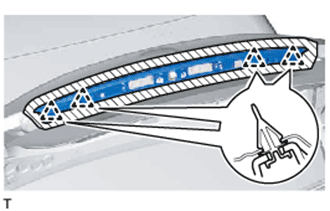
REMOVE REAR SPOILER SUB-ASSEMBLY (w/ Rear Spoiler)
Tech Tips
When removing the rear spoiler, heat the vehicle body and rear spoiler using a heat light.
Standard Item Temperature Vehicle Body 40 to 60°C (104 to 140°F) Rear Spoiler 20 to 30°C (68 to 86°F) Note
Do not heat the vehicle body or rear spoiler excessively.
-
Remove the 2 nuts.
-
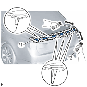
Put protective tape around the rear spoiler.
-
Insert piano wire between the vehicle body and rear spoiler.
Tech Tips
Be careful of the bolt positions.
-
Tie objects that can serve as handles (for example, wooden blocks) to the piano wire ends.
-
Pull the piano wire and scrape off the double-sided tape that holds the rear spoiler to the vehicle body.
Note
Be careful not to damage the vehicle body.
-
Detach the 5 clips and remove the rear spoiler.
Text in Illustration *1 Protective Tape *2 Wooden Block
-
-
REMOVE REAR LIGHT ASSEMBLY LH
-
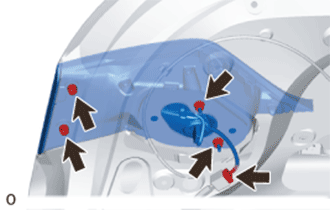
Remove the 4 nuts and rear light assembly LH.
Note
-
When removing the rear light assembly LH, be careful not to damage the clip.
-
If a clip is damaged or becomes detached from the vehicle, replace it with a new one.
-
-
Disconnect the connector.
-
-
REMOVE REAR LIGHT ASSEMBLY RH
Tech Tips
Use the same procedure described for the LH side.
-
REMOVE NO. 3 LUGGAGE COMPARTMENT DOOR OUTSIDE GARNISH
-
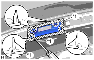
Text in Illustration *1 Protective Tape Put protective tape around the No. 3 luggage compartment door outside garnish.
-
Using a screwdriver, detach the 4 claws and remove the No. 3 luggage compartment door outside garnish.
Tech Tips
Tape the screwdriver tip before use.
-
-
REMOVE NO. 2 LUGGAGE COMPARTMENT DOOR OUTSIDE GARNISH
Tech Tips
Use the same procedure described for the No. 3 luggage compartment door outside garnish.
-
REMOVE LUGGAGE COMPARTMENT DOOR OUTSIDE GARNISH SUB-ASSEMBLY
-
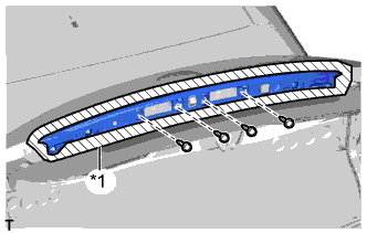
Text in Illustration *1 Protective Tape Put protective tape around the luggage compartment door outside garnish.
-
Remove the 4 screws.
-
Detach the 4 clips and remove the luggage compartment door outside garnish.
-
-
REMOVE REAR TELEVISION CAMERA ASSEMBLY
-
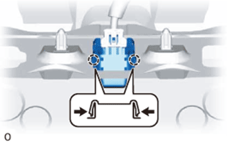
Pull the rear television camera assembly to detach the 2 claws on the outside of the rear television camera assembly.
-
Disconnect the connector and remove the rear television camera assembly.
-
-
REMOVE LUGGAGE ELECTRICAL KEY SWITCH
-
Disconnect the connector.
-
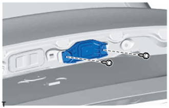
Remove the 2 screws and luggage electrical key switch.
-
-
REMOVE LICENSE PLATE LIGHT ASSEMBLY
-
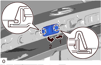
Detach the 2 claws as indicated by the arrows in the order shown in the illustration and remove the license plate light assembly.
-
Disconnect the connector.
-